BoardNode prototype
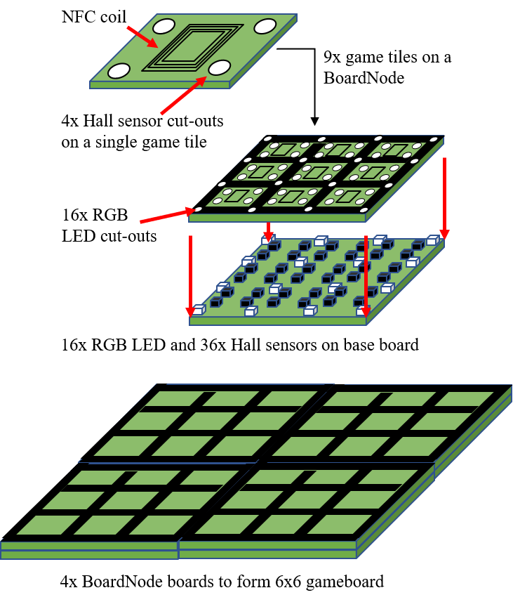
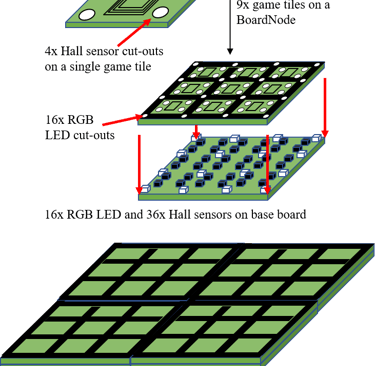
Prototyping a modular electronic gameboard with tiles that have RGB LEDs for gamestate indication, NFC sensing for gamepiece identification, and Hall sensors for gampiece orientation detection. Each BoardNode is made to be 9x9 tiles, and to fit a 16x16 studs LEGO plate, enabling easy customization. Multiple BoardNodes can be connected to a Controller to form a larger gameboard
In addition to enjoying making things with electronics, I also enjoy playing board games. When my kids recently got old enough to start playing with LEGO, I started thinking about how I could combine all of these interests into a project. I landed on the idea of making a board game platform enhanced by electronics and using LEGO for game pieces and possibly even game board elements.
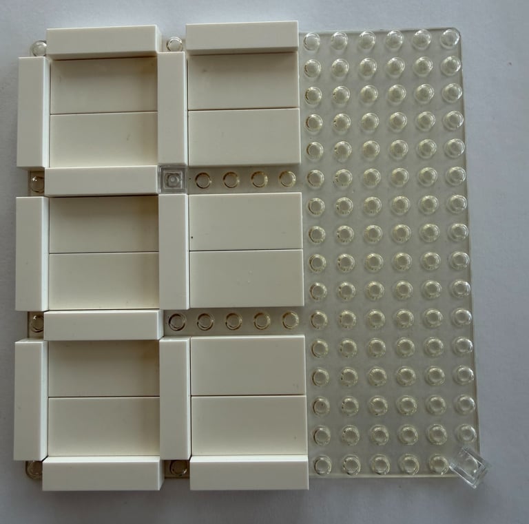
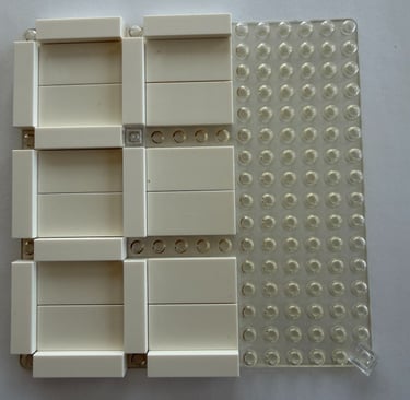
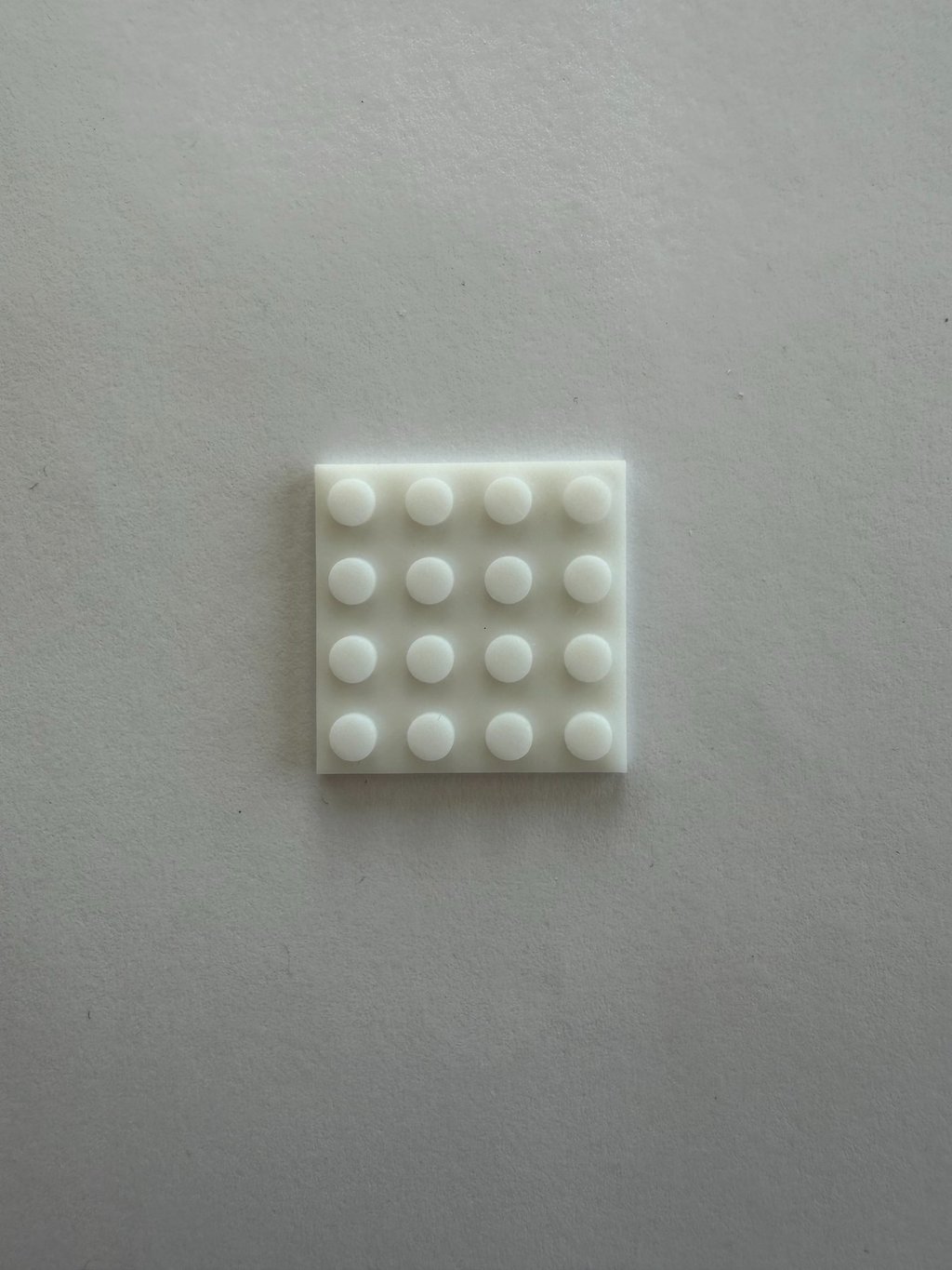
After weighing several approaches and researching different existing LEGO games, I came across transparent LEGO baseplates. They seemed useful for LED backlighting. Further research revealed that LEGO itself no longer produces these, though they are still available from third-party vendors. I also found that they are mostly available in the 16×16-stud variant.
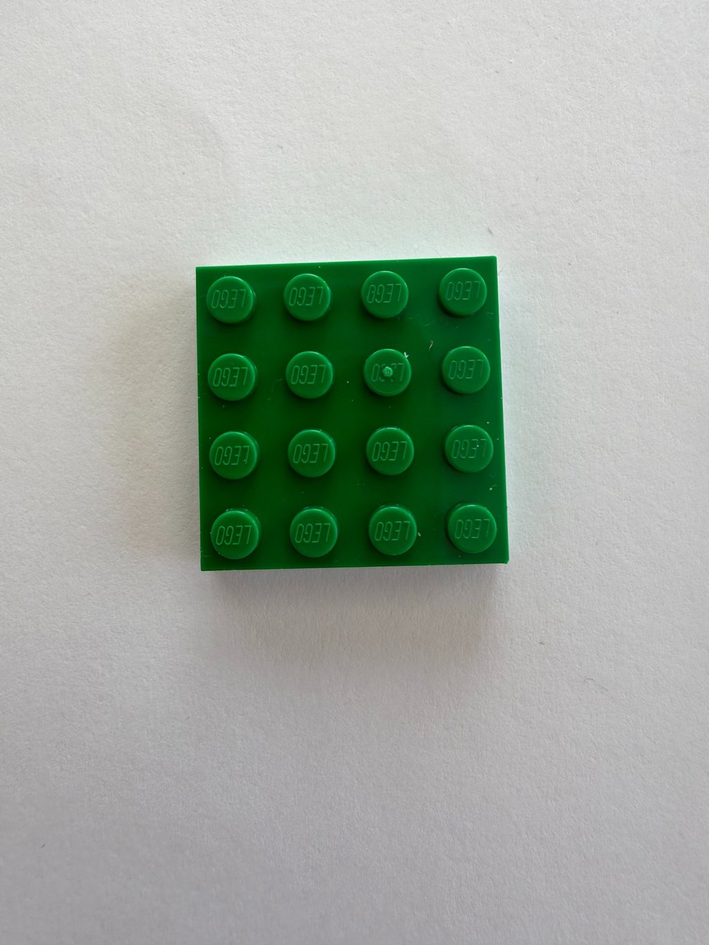
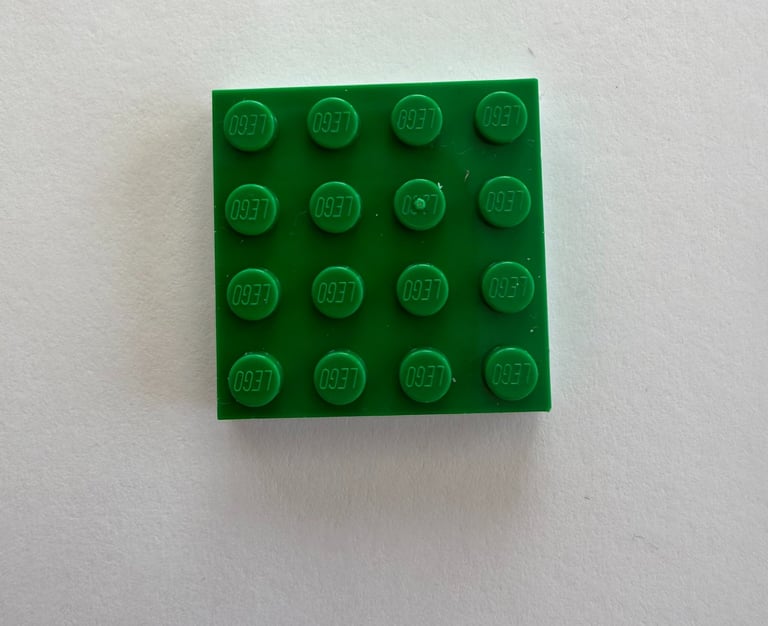
Given that LEGO minifigures typically fit comfortably on a 4×4-stud base, a 16×16-stud baseplate would be perfect for creating a 3×3 grid of game tiles, where each tile is 4×4 studs and separated by one stud. This also made it possible to use transparent bricks in positions where I wanted LED lighting.
To compensate for the relatively small 3×3 grid, I decided to introduce both NFC sensing for game piece identification and Hall sensors for game piece orientation sensing. I also envisioned that multiple of these 3×3 boards — which I started calling Board Nodes — could be connected together to form, for example, a 6×6 grid.
Electrically, this meant designing circuit boards that fit beneath a 16×16 LEGO baseplate, with nine NFC antennas arranged in a 3×3 game tile grid, LEDs at the corners of each game tile, and four Hall-effect orientation sensors for each tile. In total, this resulted in 36 Hall sensors, 16 RGB LEDs, and 9 antennas multiplexed to a single NFC reader — all exposed through an external interface for a game controller.
For the game controller, I ultimately defaulted to the easiest and quickest solution I could think of: a Raspberry Pi. I debated for a while exactly how the external interface should be implemented, but in the end I settled on serial communication over USB for the prototypes. This allowed for easy connections using readily available USB cables, straightforward interfacing with a PC for development and debugging, and simple integration with, for example, a Python script running on a Raspberry Pi.
The LEGO pieces add a bit of height to the game board, and importantly, between the game pieces and the sensing electronics beneath. It is therefore important to place the sensors as close to the LEGO baseplate as possible. The NFC antennas are not designed for long detection distances, so they must be flush with the back of the LEGO baseplate. The Hall sensors also need to be positioned close to the baseplate; otherwise, larger magnets would be required in the game pieces to ensure reliable detection. However, larger magnets create wider magnetic fields, which increases the risk of being detected by multiple sensors unintentionally.
The concept I chose was to split the design into two PCBs: one containing the antennas and NFC interface, and another placed directly beneath it that holds the LEDs, Hall sensors, and the rest of the electronics. Cut-outs in the top PCB make room for the LEDs and Hall sensors, allowing both the antennas and sensors to sit directly beneath the LEGO baseplate.
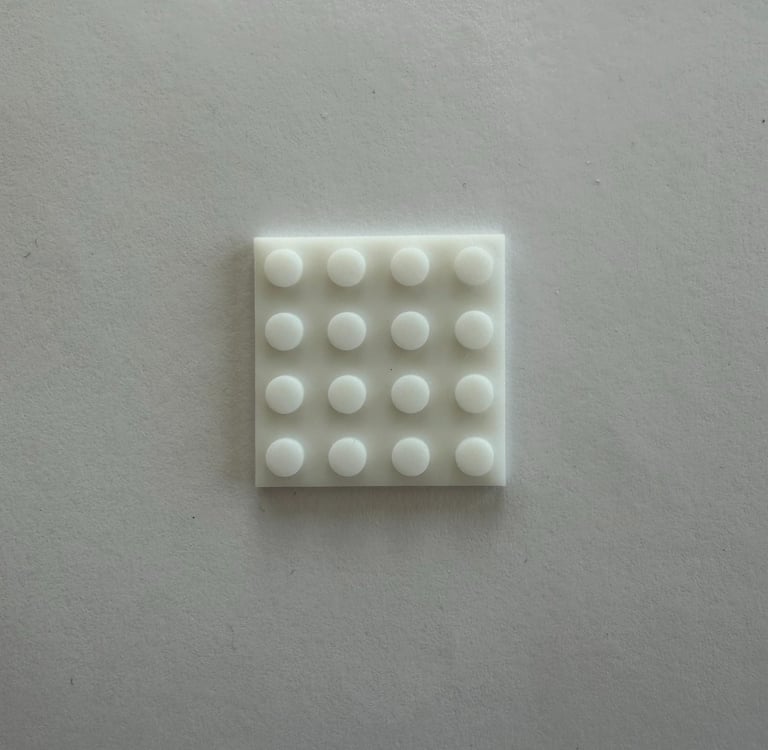
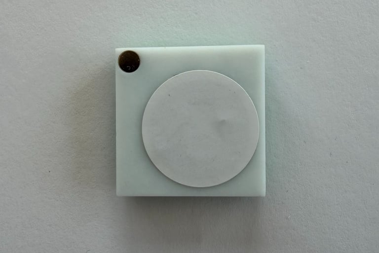
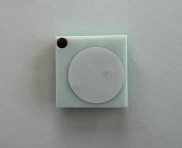
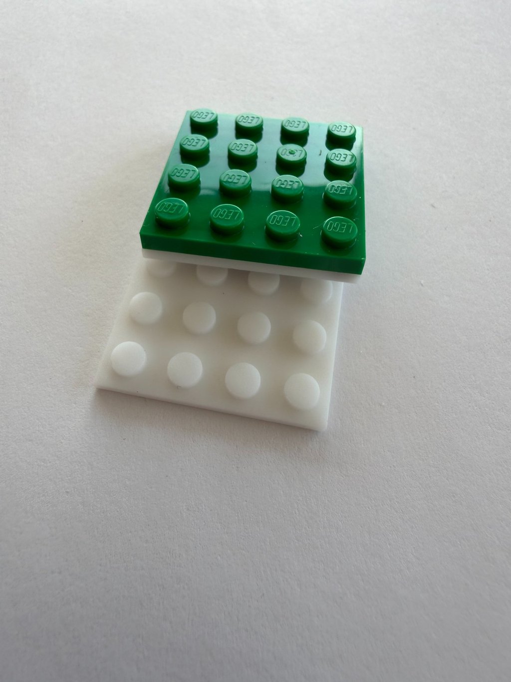
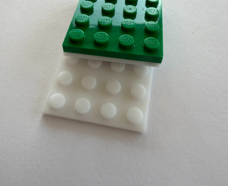
To complement this, I designed and 3D-printed a game piece base with internal cavities for a magnet and an NFC tag, as well as studs on top for attaching a 4×4 LEGO plate.
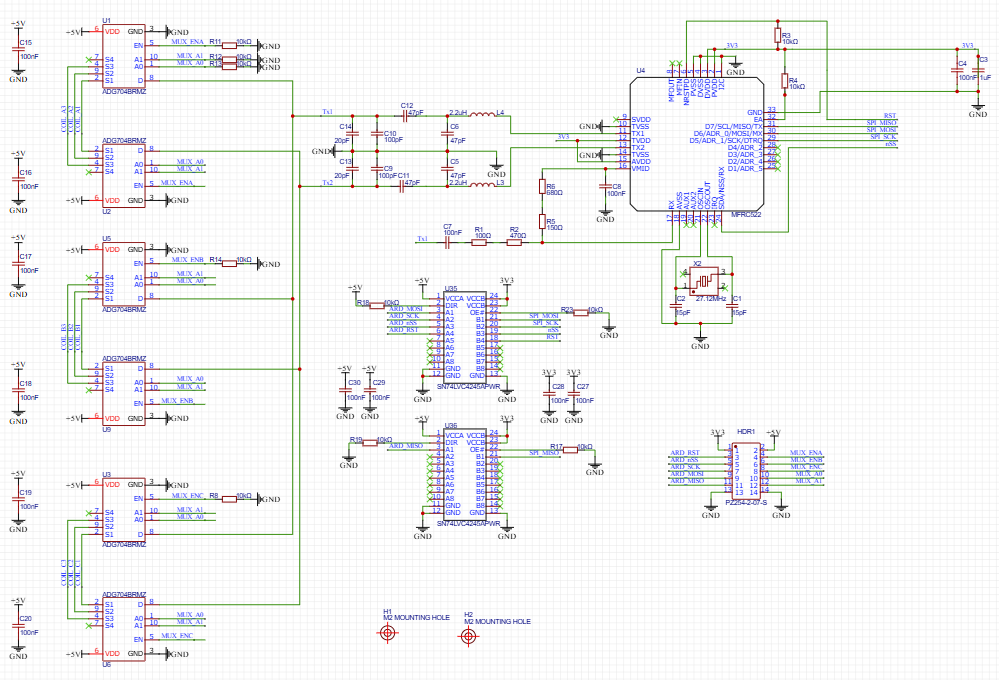
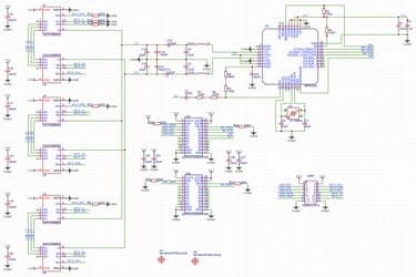
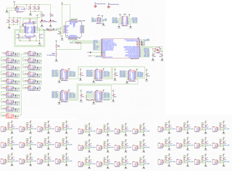
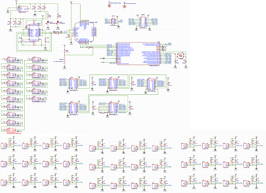
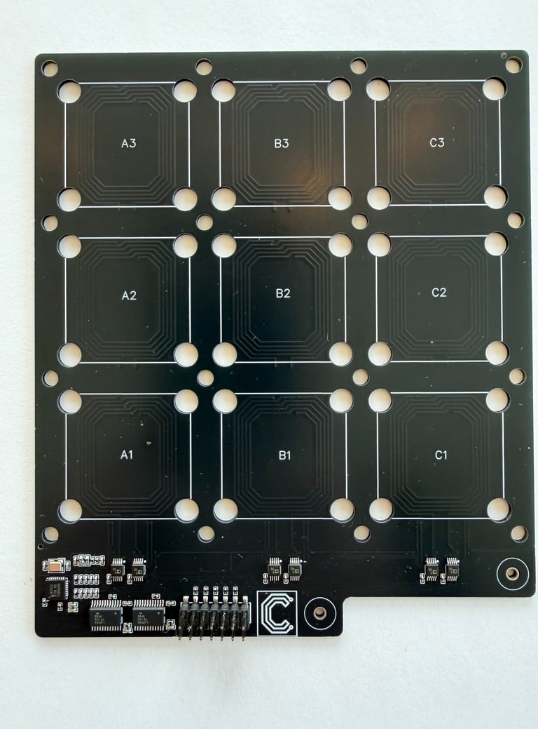
With the concept in place, it was time to start designing the electronics. The schematic for the NFC PCB is very much a copy of my previous project, multiplexing NFC antennas, with some adjustments to make it a 3x3 grid instead of the original 2x4 grid, as well as a pin header for connecting to the Hall and LED layer PCB:
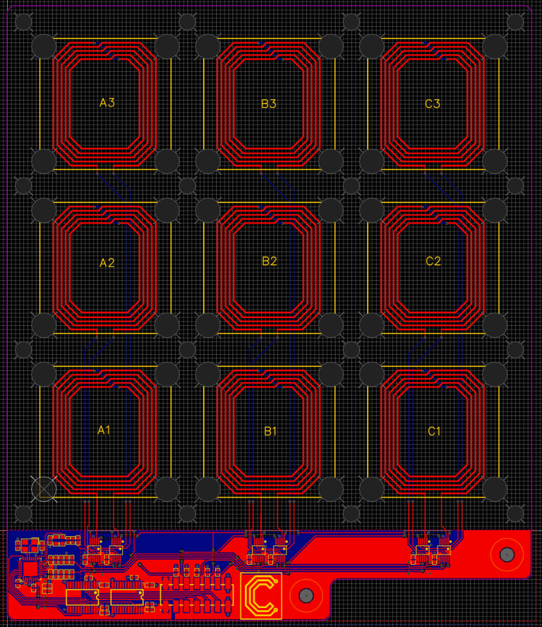
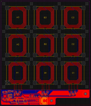
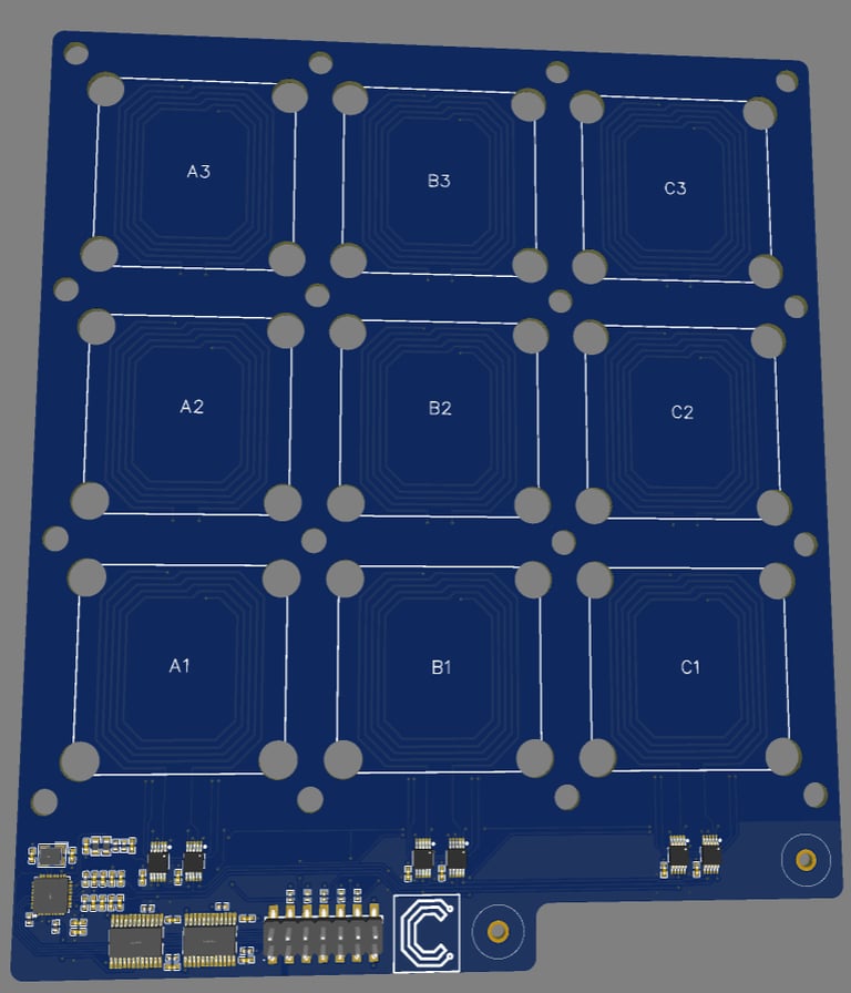
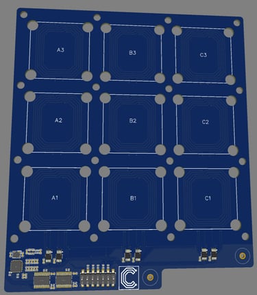
The layout similarly reuses much of that design, but adapted to a new board shape and antenna grid. The cut-outs / holes for the LEDs and Hall sensors are also introduced here, as well as a couple of mounting holes.
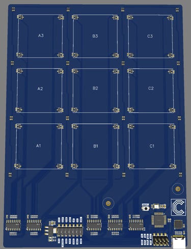
The Hall and LED PCB design reuses an ATmega328P microcontroller and a USB-C interface design I’ve used in many other projects. The 16× WS2812B RGB LEDs I chose are sized to fit within the available cut-outs in the NFC PCB. The 36 Hall sensors are too many to connect directly to the microcontroller, so shift registers are used instead to read in the Hall sensor states.
Finally, a pin header matching the corresponding header on the NFC PCB is included to allow interconnection between the two boards.
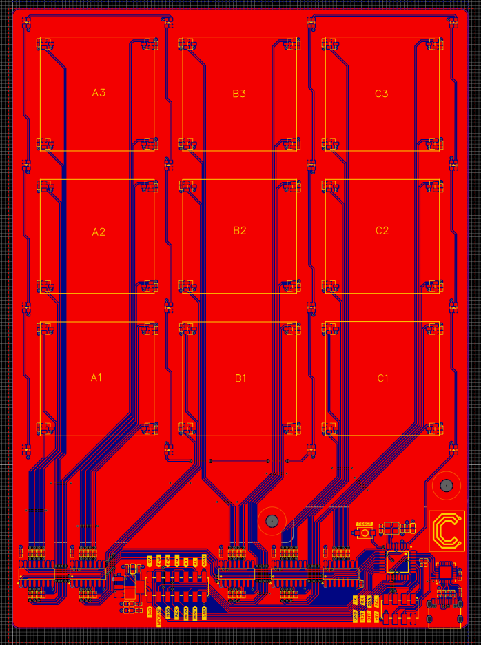
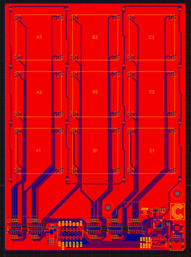
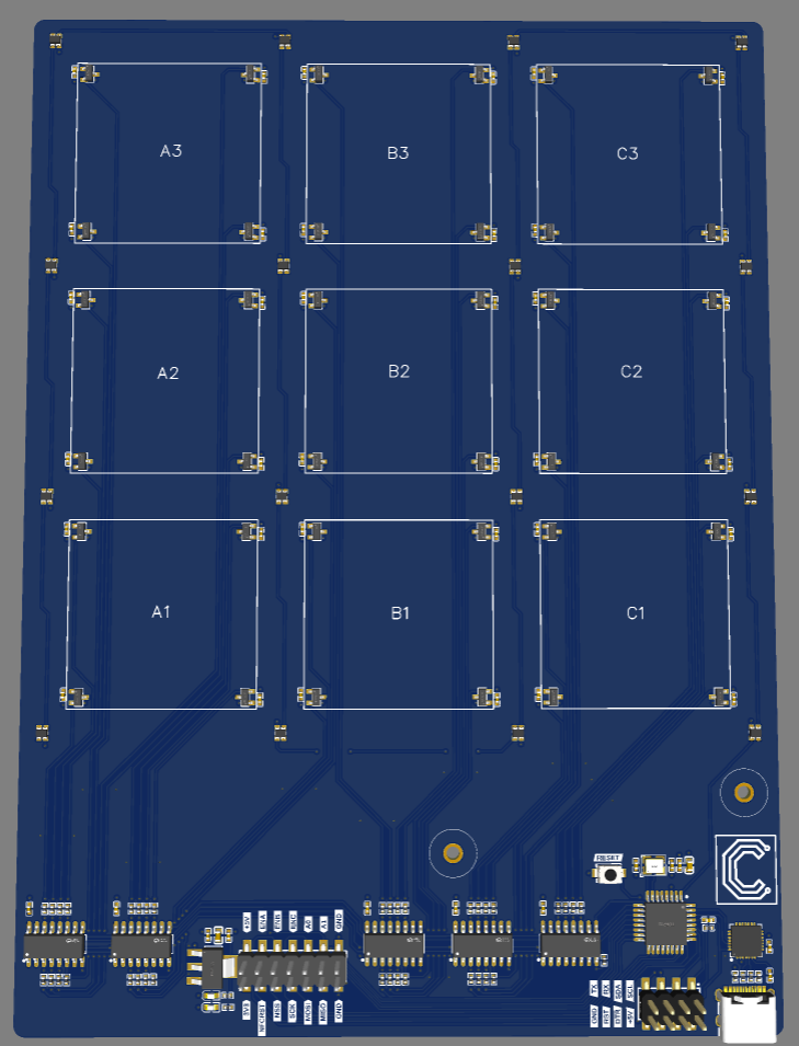
The layout is carefully matched to the physical locations I want for both the LED backlighting and the gamepiece orientation sensing on the gameboard. And the pin header and mounting holes is placed so that it lines up with the counterparts on the NFC PCB:
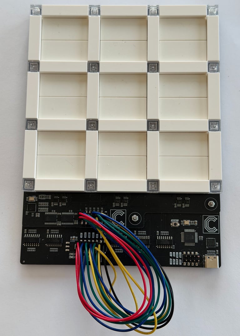
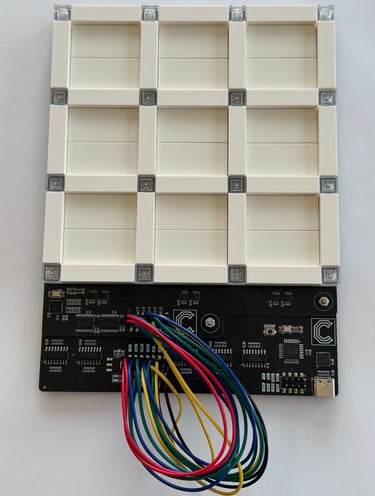
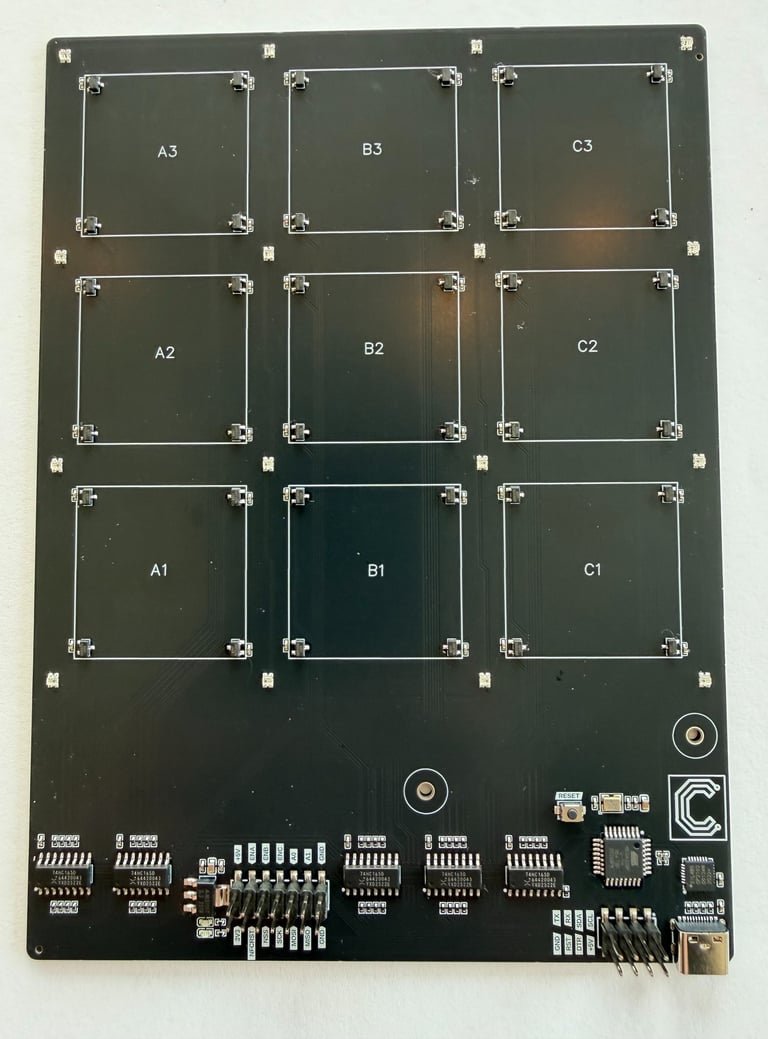
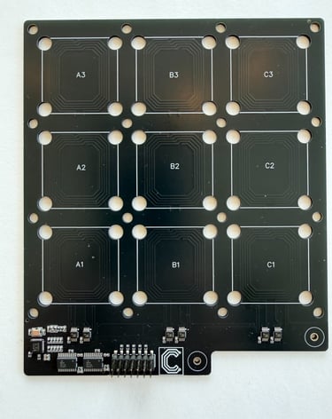
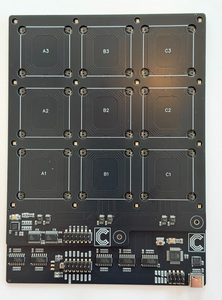
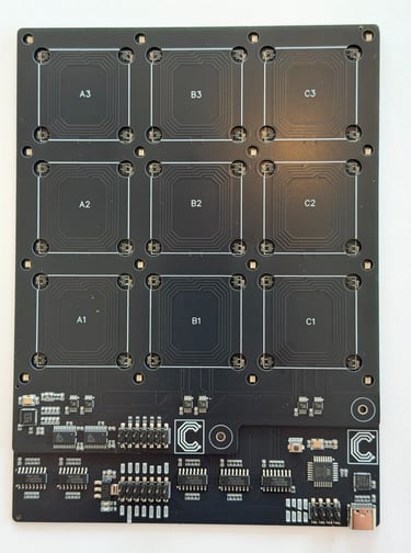
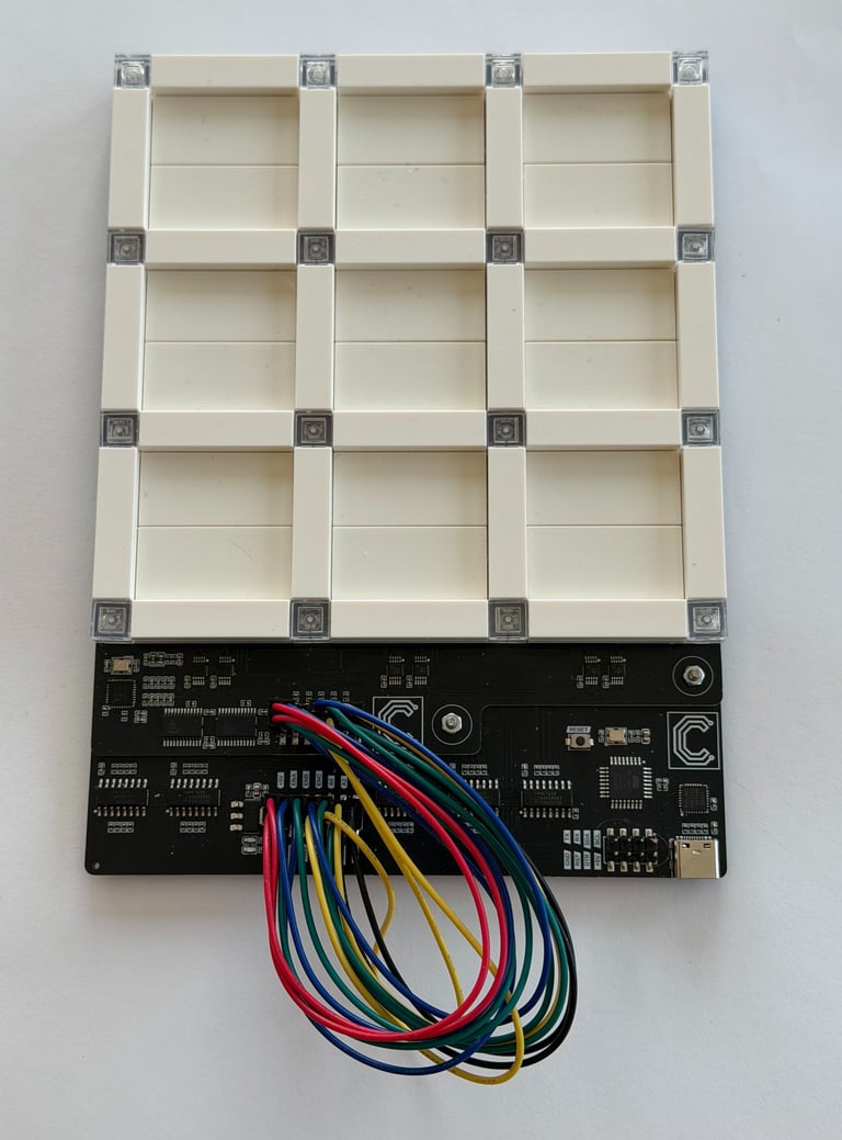
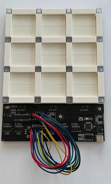
The finished and assembled circuitboards, separately and mounted together:

After flashing the bootloader onto the Atmega328P microcontroller, I wrote a test sketch that checked for occupancy by looking for Hall sensor activation, and for ID by checking occupied tiles for presence of a NFC tag. Then LEDs lit up based on the findings and indicates the sensed result. The first gif shows how detection of orientation lights up red LEDs based on where "forward" of the gamepiece points. The second gif shows how the NFC tags colors the tiles green or blue based on the individual NFC tags on the bottom of the gamepieces.
With this basis in place, the first building block for a modular electronics enhanced LEGO themed board game is ready. The next part will likely be to assemble three more of the prototype BoardNodes and combine them to a 6x6 grid, and hook it up to a game controller and design a demo application.
Circuithings
It's all about circuit things.
contact@circuithings.com
© 2025. All rights reserved.
Contact