Creating and Programming a custom PCB with an STM32H5
4/8/20269 min read
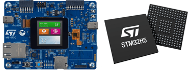
There's a huge range of microcontroller options for STM32 with wildly different price points. The low-end parts can be very cheap, while the high-end parts such as H7 is more expensive. And for every part, there's options for choosing specific combinations of package, flash size, RAM, and peripherals, which leads to there being a very large number of parts available. So which one to choose for our custom board? While all the STM32 parts are based on different ARM Cortex-M variants, such as Cortex-M0, M0+, M1, M3, M4, M7, M23, M33, it seems like there's a consolidation around the M33 variant of the Cortex variants in the latest releases. These are the STM32U5, STM32H5, and the STM32C5 families. The U5 is for ultra-low-power, the C5 for cheap general purpose, and the H5 is for high performance. For this post I will choose the H5, mainly because I personally find the high performance variant most interesting and flexible for coming use-cases in my projects.
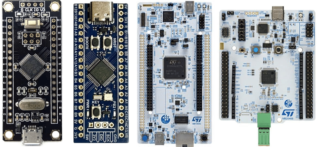
This is a follow-up to my previous walkthrough on making custom ATmega328 and ESP32-C3 development boards. Designing a custom board with an STM32 microcontroller is often the next step after working with the ATmega328 and ESP32. The reason is that STM32 microcontrollers are more complex and require a bit more care to get working, but they are still very accessible through popular and inexpensive development boards such as the Blue Pill and Black Pill. As a result, they are well known in the maker and hobbyist communities.
People often hit a wall with ATmega328-based boards like the Arduino Uno when it comes to processing speed and available program memory. ESP32 development boards, on the other hand, are very easy to use and offer much faster processors and significantly more memory. On top of that, they provide built-in Bluetooth and Wi-Fi capabilities. However, you often end up relying on high-level libraries and networking stacks, and they are not very energy efficient. Some functionality is provided by Espressif (the company behind the ESP32) in the form of “binary blobs”—precompiled code that you cannot inspect or modify.
As you begin to use a wider or more specialized range of peripherals, the ESP32 can start to show its limitations. Another constraint is the number of available GPIO pins, which can be relatively limited depending on the module. Additionally, projects that do not require wireless connectivity may not fully utilize the ESP32’s primary strengths. The ESP32 is fundamentally a Wi-Fi/Bluetooth SoC, whereas the STM32 is a general-purpose microcontroller family.
The ESP32 is a great choice when you need Wi-Fi or Bluetooth, want fast prototyping, and care more about getting something working quickly than optimizing for efficiency or precision. The STM32 family, on the other hand, is vast and spans everything from low-cost general-purpose chips for consumer products, to ultra-low-power variants for wearables, to high-performance and specialized devices. It also offers strong long-term availability, which is important for both companies and hobbyists.
Where the ESP32 ecosystem is very maker-friendly—with Arduino core support and countless tutorials for Wi-Fi web servers, MQTT, HTTP, ESP-NOW, BLE, Home Assistant/ESPHome, and more—the STM32 ecosystem is built around professional-grade tooling such as STM32CubeIDE, STM32CubeMX, and the HAL/LL libraries. These are excellent for structured embedded development but can feel more complex at first. There is Arduino core support for some STM32 boards, but it is generally more mature and widely supported on the ESP32 platform.
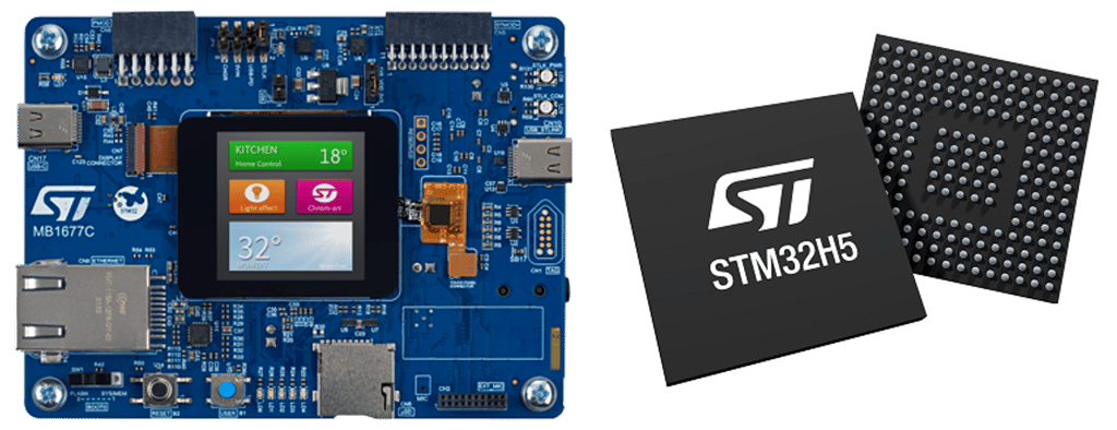
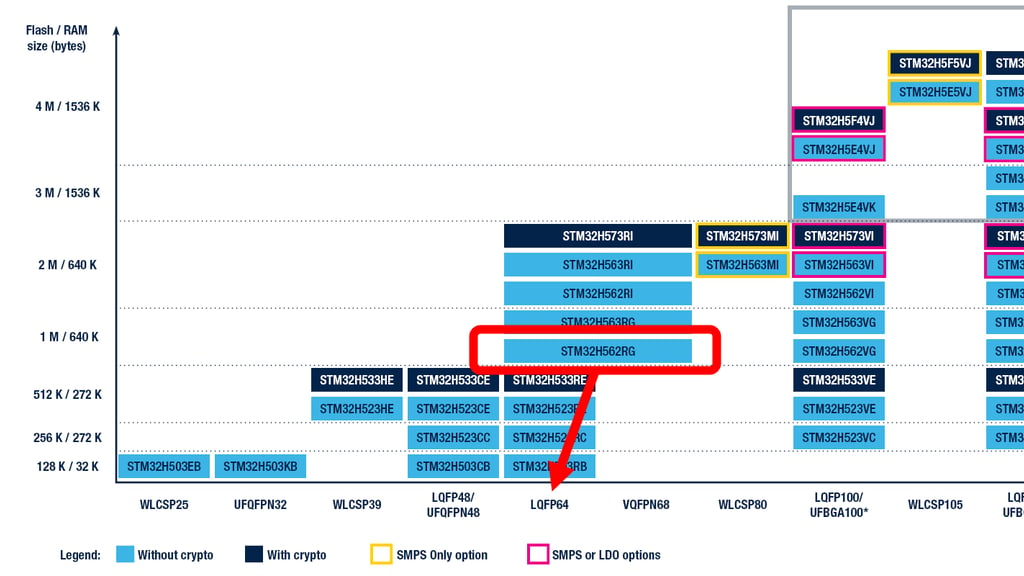
The STM32H5 family has multiple options to choose from. But since I'm going to use JLCPCB's assembly service, I'm already limited to the ones that are stocked in their inventory in large enough numbers to also make possible more designs with it at a later date, which at this time is the STM32H503, STM32H562, STM32H573. The 503 is the cheapest with least amount of memory, while the 562 and 573 has equal memory and mostly differ on more encryption and security options for the 573. I'm therefore choosing the STM32H562 as I'm in no need of spending more money for encryption and security options that I won't need in hobbyist and maker projects. And specifically the STM32H562RGT6 which comes in the LQFP-64 package.
It's important to distinguish between the hardware used for programming in Arduino with the Atmega328 and the ESP32, and the STM32. The custom Atmega328 had to have a one-time-use In-Circuit-Programming interface made available to flash the Arduino bootloader onto the chip before it could be programmed directly over USB connection if there is a USB-to-serial chip on the custom PCB that again translates from the USB datalines to the serial interface on the Atmega328.
The ESP32 comes with an Arduino bootloader already in place, and native USB support, and only requires a user button to be pressed to enter flashing mode, and can be programmed from Arduino IDE directly over an USB connection.
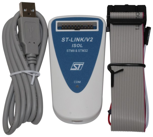
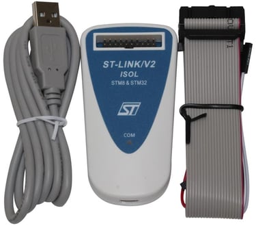
The STM32 uses a different approach. It has a dedicated programming and debugging interface called Serial Wire Debug (SWD), along with a programmer/debugger such as ST-LINK, which translates USB from your PC into SWD signals. The Arduino IDE supports uploading code via SWD using ST-LINK, and this is often the easiest way to program STM32 chips, and the one I'm going for in this post.
There are inexpensive ST-LINK clones available, but I’ve found that the older ST-LINK V2 is a good choice—it works well for hobbyist use and is relatively affordable.
So the first thing to do when making a schematic for the STM32H562RGT6 is to look at the reference design in the official documents. The easiest way to find a complete reference design is to look at the "AN5711 Application Note: Getting started with STM32H5 MCU hardware development" and the datasheet for the all the STM32H562xx parts. We're looking for the pinout of the specific package, the power and decoupling requirements, the programming interface, the crystal selection requirements, and the remaining GPIO pins that need special circuitry.
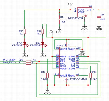
I'm re-using the USB-C schematic block with 5V-to-3V3 LDO that I've used in several other projects, and connecting the datalines to the pins PA11 and PA12 according to the datasheet pinout.

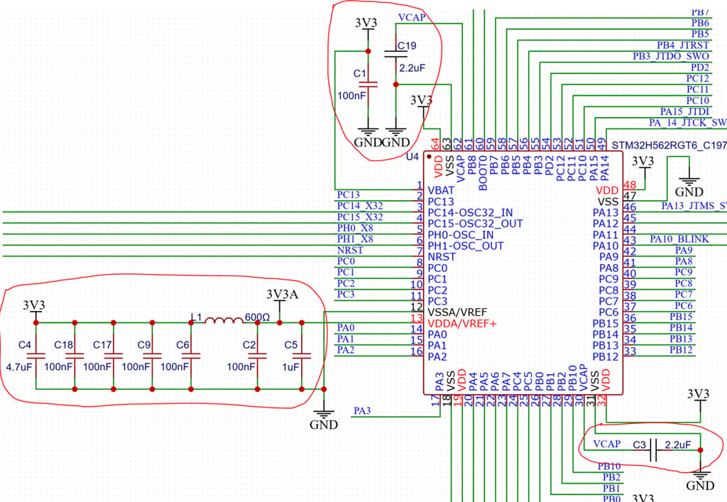
The power and decoupling requirements can be found at the Electrical Characteristics section in the datasheet, specifically in the "power supply scheme with LDO" part (I'm looking at the datasheet DS14258, Rev 6, and here it is found on page 126). Here it shows which decoupling capacitors are needed on the various pins. It does however not really give us a detailed enough guide for our specific package type, and that's where it's useful to consult "AN5711 - Getting started with STM32H5 MCU hardware development". As an example, AN5711 tells us that "For STM32H5xx devices, VREF- and VREF+ pins are not available on all packages. When these are not available, they are bonded to VSSA and VDDA, respectively" - which is exactly our case with the LQFP-64 package. The reference design schematic shown in the AN5711 is for a LQFP144 package, but there's enough information given in the various sections that when combining the datasheet and AN5711, I've ended up with the following
2x 2.2 uF on the VCAP pins - and tying the VCAP pins together
4x 100nF on the VDD pins (one for each pin) and 1x 4.7uF shared between them
1x 100nF for the VBAT pin
1x 100nF and 1x 1uF for the VREF pin - and a Ferrite bead between VDD and VFREF
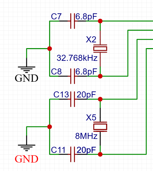
It is recommended to add a High Speed External (HSE) crystal to the design as that will improve the rate on the main system clock in the micrcontroller. The default High Speed Internal (HSI) clock signal is generated from an internal 64 MHz RC oscillator in the microcontroller package. The HSI RC oscillator has the advantage of providing a clock source at low cost (no external components). It also has a faster startup time than the HSE crystal oscillator. However, even with calibration, the frequency is less accurate than an external crystal oscillator or ceramic resonator. After consulting the crystal selection guide is given in section "5.3.8 - External clock source characteristics" in the datasheet, and "Figure 30. Typical application with an 8 MHz crystal", I ended up choosing an inexpensive 8MHz crystal from JLCPCBs basic part assembly library that needed 20pF load capacitors.

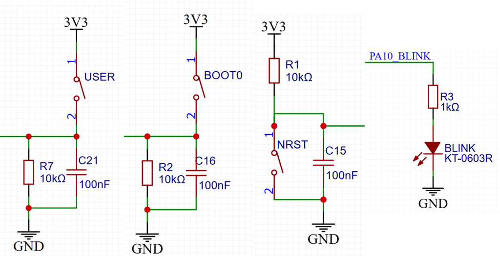
The Reset pin has to be pulled high with a 10k resistor, and resetting the chip can be made available for us by adding a pushbutton that shorts to ground. A 100nF capacitor is added to add some debounce filtering. The BOOT0 pin should also be made available for us, as it is used for entering BOOT mode where code actually can be uploaded. The microcontroller enters this code upload BOOT mode if the BOOT0 pin is high during chip startup, while it executes the uploaded code if the BOOT0 is instead low at startup. The default we want at startup is to have code execute, so the design is inverted from the Reset button, with a pulldown and a capacitor to ground, and the BOOT button shorts up to 3.3V. The BOOT button is not needed if you are going to program with the SWD interface (as we will be doing) but there exists cases where the firmware disables SWD pins or crashes immediately after reset. And then being able to boot into system memory instead of our firmware is useful for recovery. But there's commercial STM32 based board that doesn't break out the button, or just exposes a solder bridge pad, exactly because it is not needed when SWD is the only method being used for development and manufacturing. A User button and a Blink led is also added as it is always useful to have for debugging.
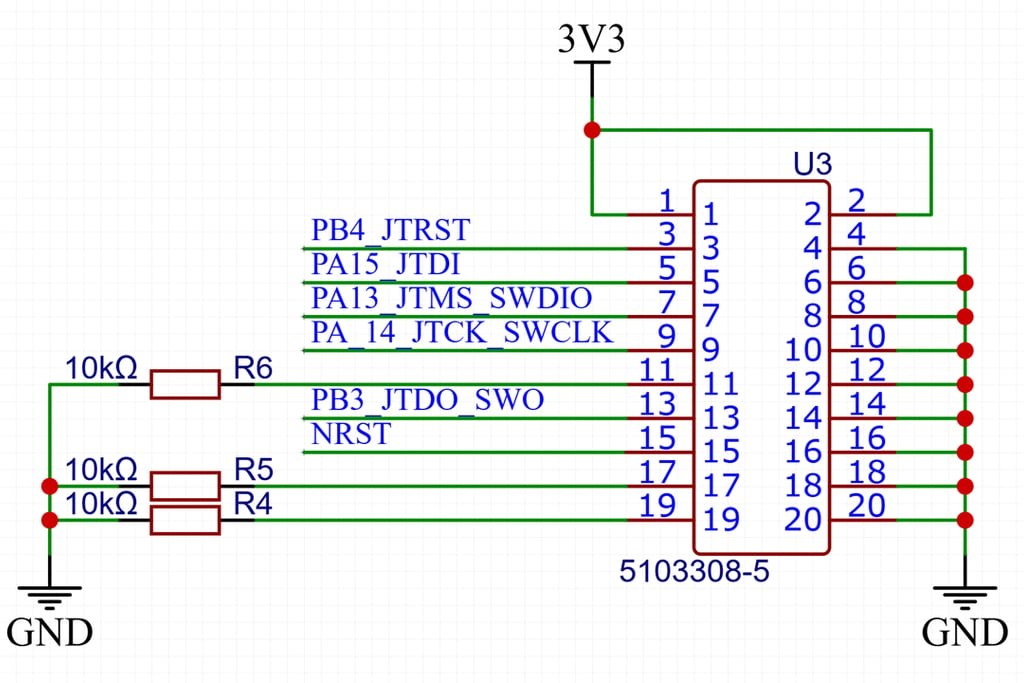
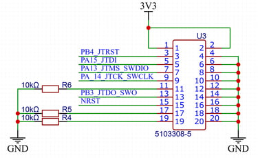
The Programming interface on some development boards are just 4 pins - Power, Ground, SWD and SWCLK. This is the bare minimum to have available for programming the STM32 chips. Other interfaces I've seen includes a fifth pin with NRESET. Most of these minimal variants are meant to save board space and instead have us use dupont wires to connect the PCB to the ST-LINK programmer. The standard ST-LINK V2 programmer comes with a large 20 pin (2x10P) header that has a full JTAG interface as well as the complete SWD interface available. 11 of the pins in this 20 pin header is only ground and power, so it's not really the most optimal solution, but it is the default option. And the datasheet and getting started document show the pinout needed to make it work. It makes the connection between the ST-LINK and the development board very easy and robust, as long as there's enough space on the PCB to place this large header. The important pins for us to make sure we connect correct is the SWD pins SWDIO, SWDCLK and SWO (SWO is used for printing to the terminal when you debug) and power, ground, and NRESET.
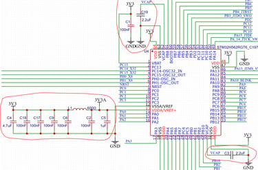
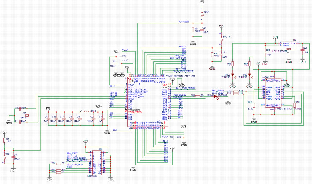
The final schematic for a development board then looks like this.
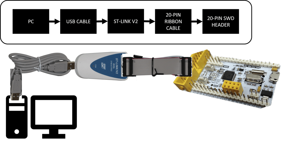
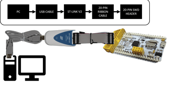
The custom PCB should be wired to the ST-LINK V2 programmer with the accompanying 20 pin ribbon cable, and the ST-LINK programmer should connect to your PC with an USB cable:
At the time of writing, I am using Arduino IDE 2.3.8.
To add STM32 support:
Go to Preferences
Add the following URL to “Additional Boards Manager URLs”:
https://github.com/stm32duino/BoardManagerFiles/raw/main/package_stmicroelectronics_index.json
Open Tools → Board → Boards Manager and install STM32 support
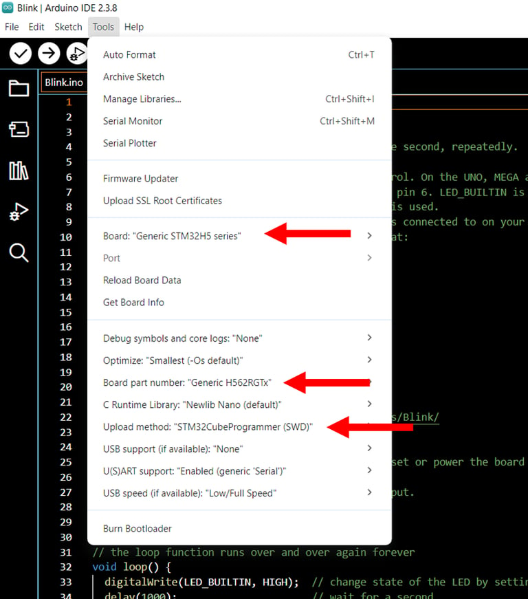
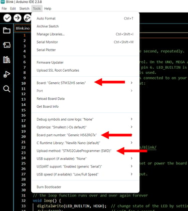
Then configure:
Board → “Generic STM32H5 Series”
Board part number → select your exact MCU
Upload method → “STM32CubeProgrammer (SWD)”
You’re now ready to upload your first sketch.
And as a final note on troubleshooting, be aware that some ST-LINK V2 units ship with outdated firmware that may not support newer STM32 families such as H5, U5, or C5. If you encounter upload errors, connect the ST-LINK to your PC, open STM32CubeProgrammer, and update its firmware.
A issue I've seen hold up people is leaving the programmer plugged into your board but not plugged into the PC. I.e. you want to make sure the microcontroller runs the code without anything other than power supplied, then you might just have unplugged everything else, but left the unpowered programmer plugged into the pin header on your board. This can in some instances (and especially on custom dev boards) cause the chip to stop executing the code.
Circuithings
It's all about circuit things.
contact@circuithings.com
© 2025. All rights reserved.
Contact