Creating and Programming a Custom PCB with ATmega328P
7/22/20259 min read
The basics of making a ATmega328 PCB compatible with Arduino - Serial and USB Communication
We want the ease of use that having an USB connection available really is. But there's no USB peripheral available on the ATmega328P, and the ATmega328P is programmed over the serial interface. The solution for this is using a USB-to-UART chip. There's multiple of them available on the market, such as CH340, CP2102 and FT232. I'm used to the CH340 so that's the one I'm throwing in here. It exists in many package types and some has more functions available, and some are really small. I like the small footprint of the CH340E variant.
For proper serial communication with the Arduino Uno or other compatible devices, proper UART connections must be incorporated into our PCB design. This includes ensuring correct connections to the RX and TX pins of the ATmega328P, which are responsible for receiving and transmitting data. These pins must be crossed with our CH340 pins, such as the microcontroller receive pin is connected to what is essentially computer transmit pin. And microcontroller transmit pin is connected to computer receive pin. Messing up these connections is a very common mistake among both beginners and veterans.
It is also essential to provide power supply connections, typically 5V and ground, to ensure that your PCB receives the necessary voltage to operate all components effectively. Since we are showing a design with USB, we'll be modern and use the USB-C type. Placing 5.1k pulldowns on each of the CC pins on the USB-C connector tells the USB power delivery protocol that we want to see 5V and will draw up to 1.5A.
The DTR (Data Terminal Ready) function is both important and easy to overlook. It's an output from the USB-to-UART chip that primarily used for automatically resetting the microcontroller when a new sketch is uploaded. It's a control signal that, when pulled low by the USB-to-UART chip, triggers a reset on the ATmega328P (or similar) chip, allowing the bootloader to run and accept a new sketch. When you connect an Arduino to your computer via USB, the USB-to-Serial chip (like FT232RL or CP2102) asserts the DTR signal low, which in turn triggers a reset on the main microcontroller. The DTR pin must be connected to the microcontroller's reset pin via a capacitor. This configuration allows for a brief pulse on the reset pin when DTR changes state, rather than a sustained low signal. The DTR pin is important as without this DTR-based reset, you'd need to manually press the reset button on the Arduino at the precise moment the upload starts, which is inconvenient (and very difficult to time right!). In simpler terms, this clever combination of DTR, a coupling capacitor, and a pull-up resistor allows clean, reliable auto-reset and upload behavior without accidental resets during normal serial use.
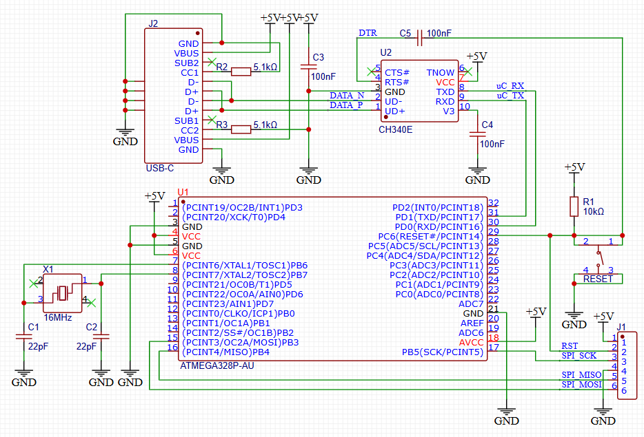
The CH340E chip doesn't have the DTR pin exposed like the CH340C or CH340G variants has, but repurposing the RTS (Request To Send) pin of the CH340E seems to work fine. The internal circuitry of the CH340E also needs a 100nF capacitor from it's V3 pin to ground to be able to work properly. Adding all of the serial/USB interface we finally end up with:
The Importance of Creating Custom PCBs
The digital era has witnessed a remarkable growth in the demand for tailored electronic solutions, making the design and production of custom printed circuit boards (PCBs) available for engineers and hobbyists alike.
Makers and beginners in electronics often find themselves in a situation where the prototype consists of an Arduino Uno / Nano / ... and a breadboard with components and wires, or a sensor module is connected to your Arduino with dupont wires. These setups are great for proof of concept and protptyping, but they can be overkill (and oversized) for finished projects. Making your own board often reduces cost per unit for final builds, significantly shrinks the size, lets you customize exactly which features and connectors are included, and probably just as important improves learning by teaching you how microcontrollers really work at the hardware level.
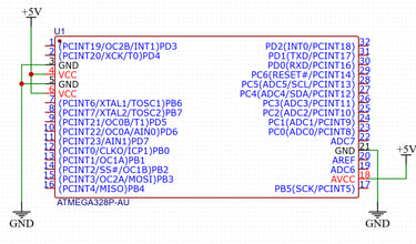
If you're building a product or doing a personal project, learning to design and program custom PCBs is a huge step forward. Chances are, you have started out with the Arduino UNO/Nano/Giga/etc., so it makes perfect sense to sticking with hardware you already are somewhat familiar with. Creating your own custom PCB using the ATmega328P microcontroller has become something of a rite of passage for electronics hobbyists and makers, and it is a satisfying step up from using Arduino boards. It opens the door to more compact, purpose-built, and professional projects. Therefore, in this post we'll walk through how to make your own ATmega328P boards, how to wire up the ATmega328P correctly, and how to program it using an Arduino Uno as an ISP. The first thing we need is to do is place the ATmega328P chip itself and connect power and ground.

The basics of making a ATmega328 PCB compatible with Arduino - Bootloader
The goal here is making a custom PCB with the ATmega328 microcontroller that can be programmed with a USB cable and have the bootloader flashed onto it with an Arduino Uno.
If you don't know what a bootloader is, here's the short of it: A bootloader on an Arduino is a small program stored in a reserved area of the microcontroller's flash memory. Its primary function is to allow the Arduino board to be programmed via a serial or USB connection, without needing a separate programmer device. Essentially, it's a small piece of code that runs when the Arduino is powered on or reset, looking for instructions from the Arduino IDE on your computer to upload a new program. If no upload is initiated, the bootloader then hands control over to the previously uploaded sketch. Bootloaders come pre-installed on most Arduino microcontroller boards, but when you make your own you have to flash it onto the microcontroller yourself. If you do not, the the Arduino IDE will not recognize your board when you connect it to your computer. The bootloader enables the Arduino IDE to communicate with the microcontroller over the serial or USB connection to upload new sketches. The way it works is that when the Arduino powers on or is reset, the bootloader starts running first. The bootloader checks if the Arduino IDE is trying to upload a new program. If it receives the correct signals (e.g., a specific sequence of bytes), it will receive and write the new code to the microcontroller's flash memory. If no upload is initiated, the bootloader passes control to the previously uploaded program (the "user sketch"). Without a bootloader, you would typically need an external programmer (like an In-System Programmer (ISP)) to load code onto the microcontroller.
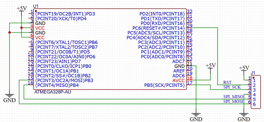
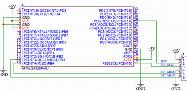
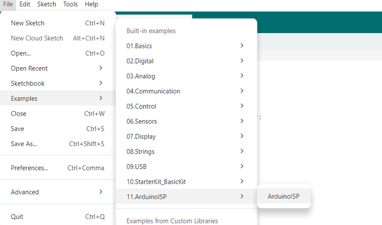
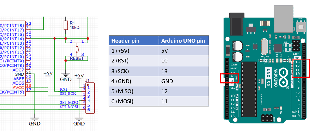
Alright, so we know we need a way to get the bootlader flashed onto our custom board, meaning we need to design in an interface on our board that allows for that. I'm going to talk about how we do it with an Arduino Uno, as the chances are pretty good that you will have one lying around. To program the bootloader and provide to the microcontroller the compatibility with the Arduino Software (IDE) you need to use an In-circuit Serial Programmer (ISP) that is the device that connects to a specific set of pins of the microcontroller to perform the programming of the whole flash memory of the microcontroller, bootloader included. Luckily for us, the people behind the Arduino system have written a sketch that lets your Arduino Uno behave as it was an ISP. This sketch is easy to find in the Arduino IDE under File -> Examples -> 11.ArduinoISP -> ArduinoISP. Inspecting this sketch shows us that the SPI interface ins MOSI, MISO and SCK is used, together with pin 10 to reset the target microcontroller. From this we see that all we need to include in our custom ATmega328 board is a connector that exposes these pins! Making room for a 6 pin male header and wiring the programming interface up gives us:
The basics of making a ATmega328 PCB compatible with Arduino - Reset
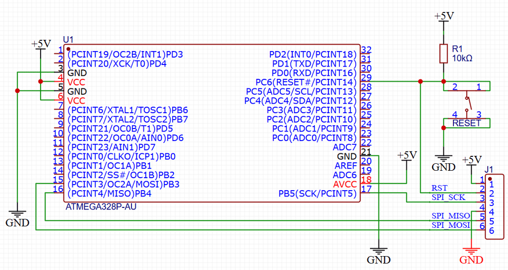
We also need to add a pull-up resistor for the reset pin (Pin 1) to ensure reliable operation of the ATmega328P during programming and normal operation. Pull-up resistors help maintain a stable high state on the reset pin, preventing accidental resets that might occur due to noise or floating pin states. The ATmega328P microcontroller looks at the state of the reset button to see if it can be programmed with new code or not. Pulling the pin low sets the microcontroller in a mode where it is accepting being flashed with new programs. A typical value for the pull-up resistor is 10 kΩ, connected from the reset pin to Vcc. It's good practice to add a button between the reset pin and ground as well to allow for manual reset of the microcontroller.
When flashing the bootloader, the Reset pin is pulled low by the Arduino Uno to allow for programming over the SPI interface. When the bootlader is flashed, we typically instead connect the serial interface (Tx and Rx pins) of the microcontroller to our computers USB port via a Serial-to-USB translator. Uploading a new sketch is then also enabled by pulling the Reset pin low, although the code upload is done via serial/USB instead since we now have the Arduino bootloader in place.
With the reset pin pulled up, we now have:
The basics of making a ATmega328 PCB compatible with Arduino - External Crystal
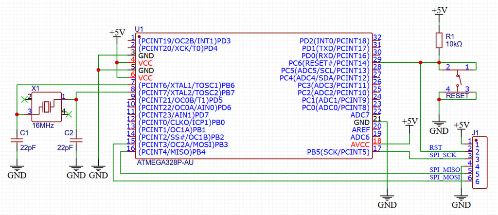
When designing a custom PCB that incorporates the ATmega328P microcontroller, it is crucial to ensure precise timing and signal stability. Two essential components for achieving these goals are an external crystal oscillator and pull-up resistors. The ATmega328P requires a stable clock signal to function optimally, and utilizing an external crystal enhances its timing accuracy beyond what is provided by internal oscillator options.
The process of wiring an external crystal oscillator follows a few straightforward steps. Generally, a crystal with a frequency of 16 MHz is recommended, as this is the standard clock speed for many applications using the ATmega328P. The crystal should be connected between the XTAL1 and XTAL2 pins of the microcontroller. Additionally, two load capacitors are typically placed from each side of the crystal to ground. The capacitor values usually range from 12 pF to 22 pF, depending on the specifications of the crystal used. It is important to refer to the datasheet of the specific crystal to determine the appropriate capacitance for optimal performance. The crystal should be placed close to the microcontroller pins. Adding it to our design, we are now at:
Flashing the bootloader with an Arduino Uno
The first thing to do is connect your Arduino Uno board to your computer and program it with the ArduinoISP sketch that you find in Arduino IDE under File -> Examples -> 11.ArduinoISP -> ArduinoISP:
And with that we're done! We have everything we need to wire up for first flashing the Arduino bootloader, followed by programming in Arduino IDE over an USB-C interface. With our setup, we'll now move on to show just how you get the bootloader flashed onto your brand new custom ATmega328P board!
Once that's done, it's time to wire up the Arduino Uno with the freshly programmed ArduinoISP sketch to you brand new PCB, as shown here in the wiring table:
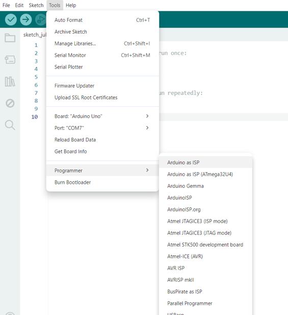
Now we're ready to do the final setup step. We need to tell the Arduino IDE that we do not intend to program the Arduino Uno we have connected, but instead use it as a programmer for a different board. The way we tell the Arduino IDE that is simply by selecting the "Arduino as ISP" option under the menu Tools -> Programmer -> Arduino as ISP:
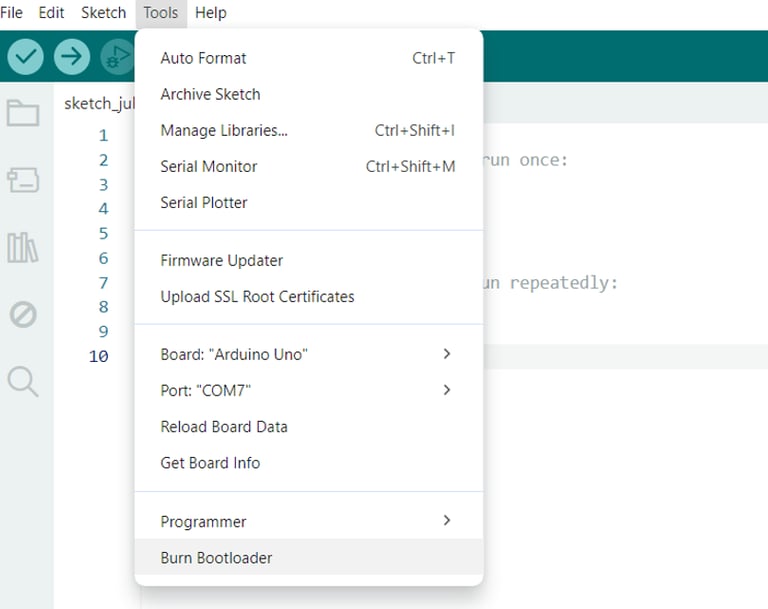
That's it! All that's left for us is to actually burn the bootloader, which is done by selecting "Burn Bootloader" under the menu Tools -> Burn Bootloader:
Once that is done, you should try uploading a a simple Blink sketch or something similar over the USB connection to verify that all works.
Circuithings
It's all about circuit things.
contact@circuithings.com
© 2025. All rights reserved.
Contact