ESP32-C3 Wordclock
Wordclock based on the ESP32-C3-WROOM microcontroller, with norwegian letters
I saw a Norwegian wordclock at a store in a local mall a while back, and thought it looked pretty cool, but it was pretty expensive. And although googling provided several results, none was with Norwegian letters. So I decided to make one for myself.
I got a ESP32 devkit lying around that I’ve gotten familiar with and found to be pretty useful for making connected devices, as well as a string of 20x WS2812B RGB-leds, and that was my first prototype. I basically tested code to connect to a public server to get the time, and controlling LEDs based on that. Once the idea was verified, next came actually deisgning the wordclock. I've been wanting to try out using patterened soldermasks as a mask for backlights for a while now, and using a PCB spacer to get uniform spacing between the base board and the mask, as well as prevent bleed between letters. The design then ended up being a Norwegian letter Wordclock made with a custom backlight board with a ESP32-C3-WROOM module, and a custom frontpanel PCB using removed soldermask and copper as mask for letters, with a hole patterned PCB as spacer. It includes buttons for i.e. setting the time manually, or other possible future menu inclusions. I regret adding silkscreen with "TIME" to them, as I found them most useful for adjusting brightness instead. Might be that a revision should be done. Power is through a powersupply with USB-C, as ESP32 is quite powerhungry and a battery wouldn't last long.
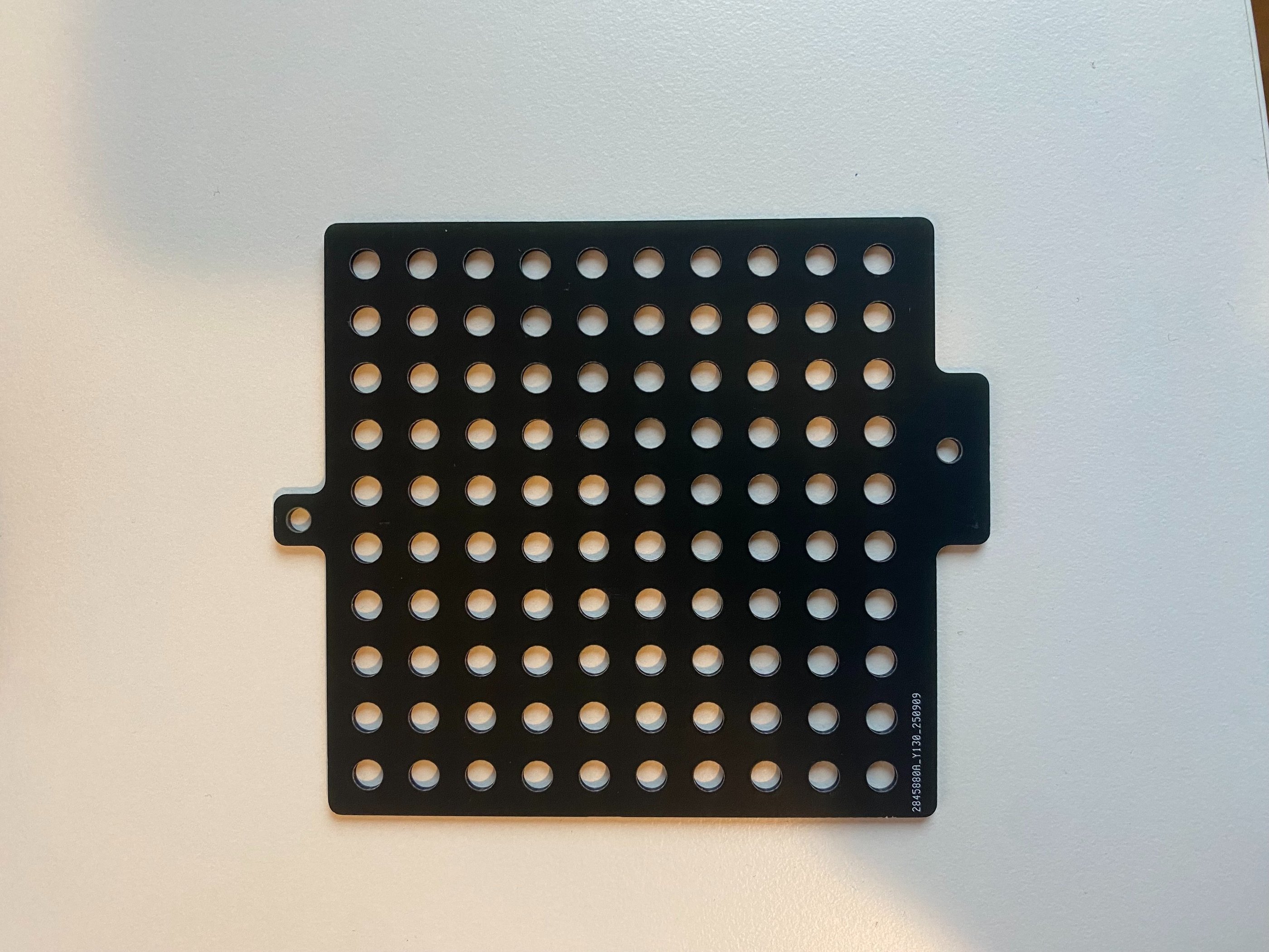
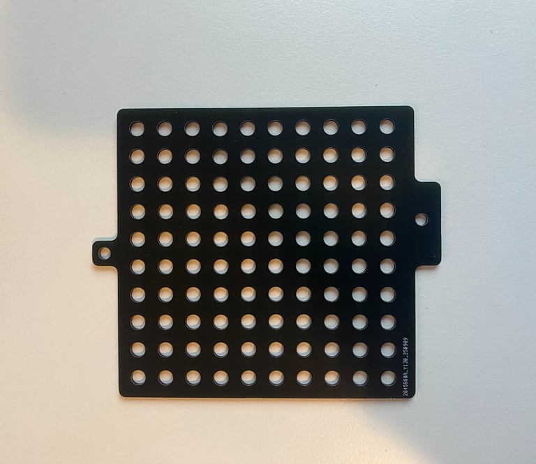
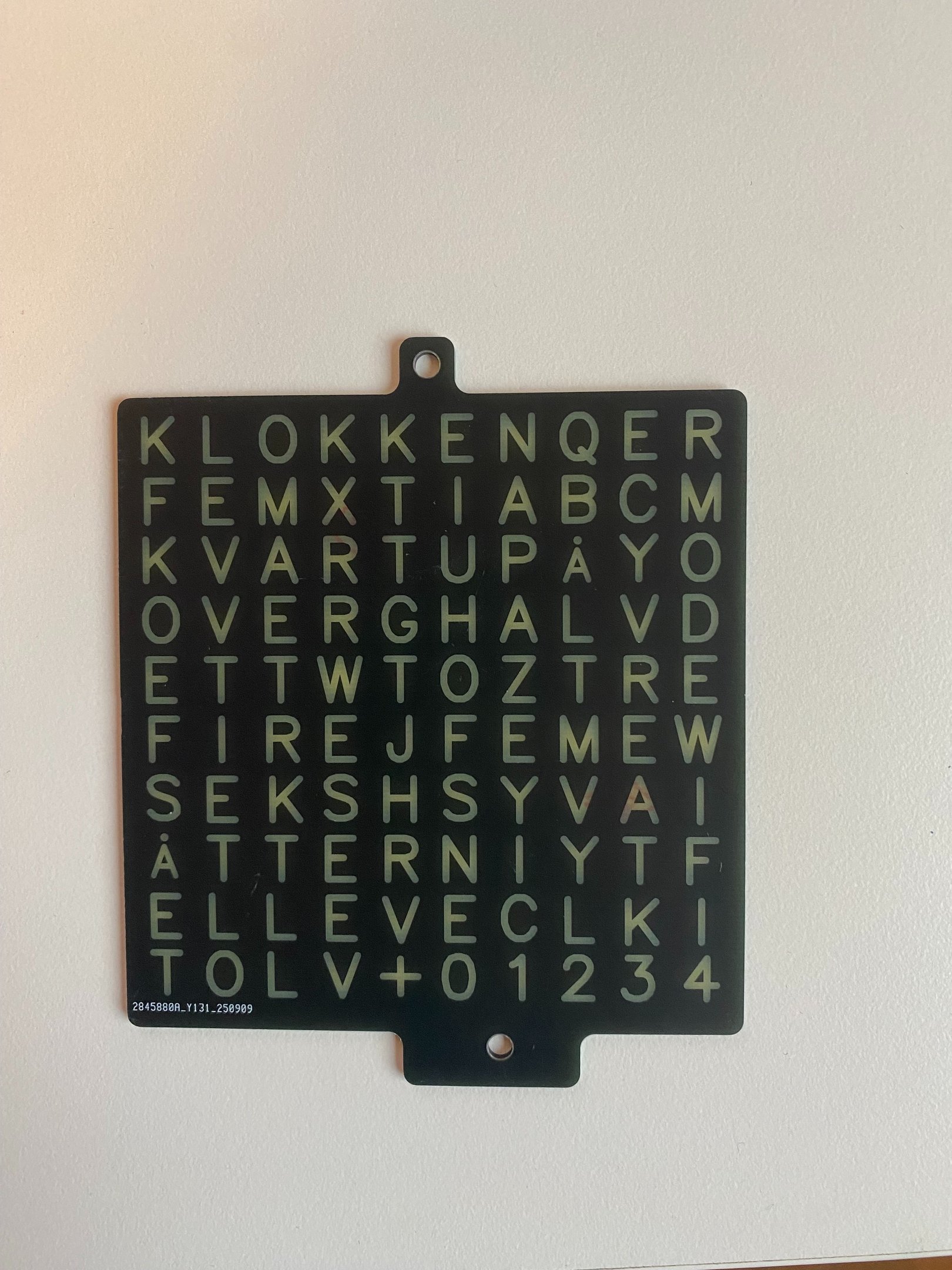
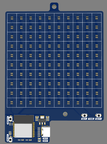
Below is the three PCBs that form the stack that makes up the clock.
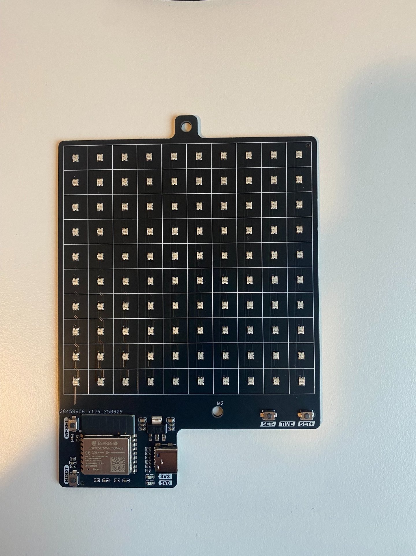
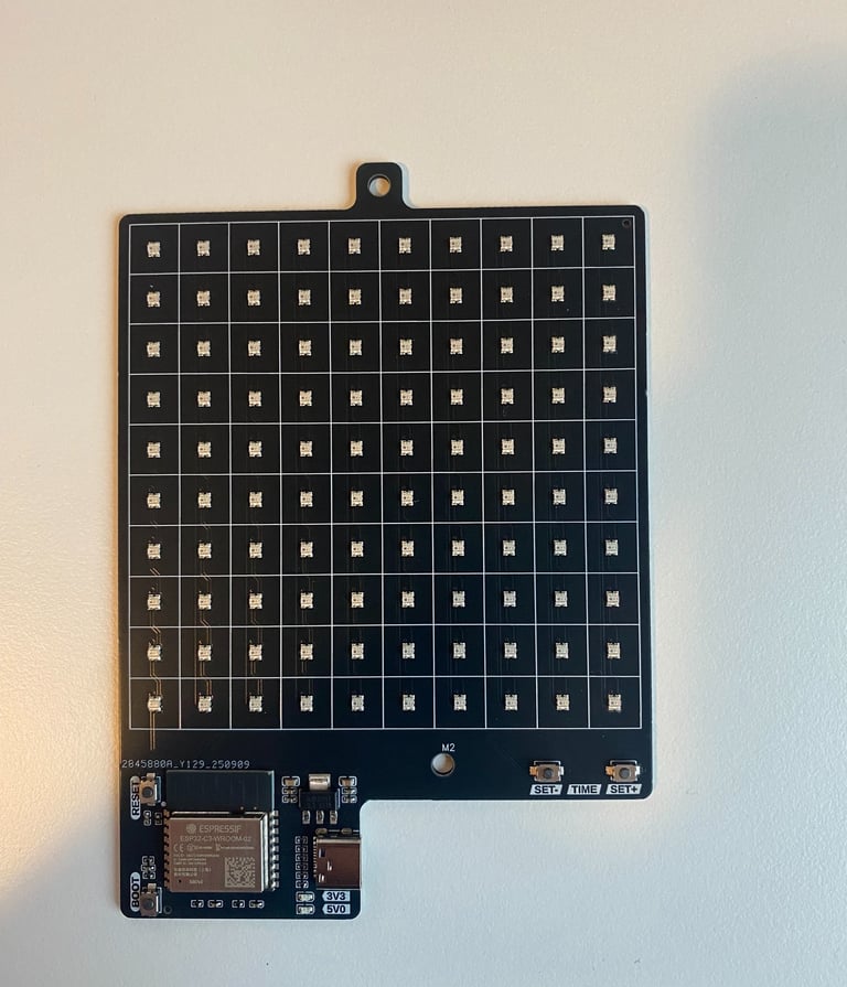
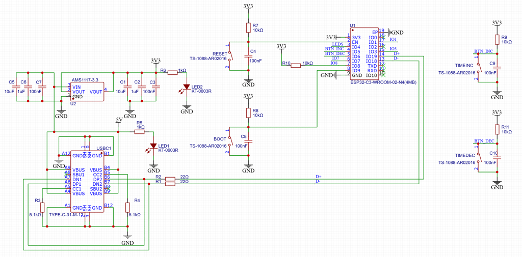
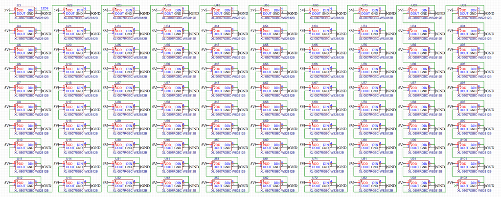
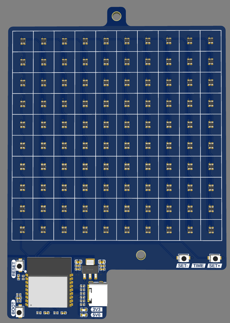
The design doesn't need many elements to works, so the schematic isn't complicated. It consists of USB-C for power and programming the ESP32. An LDO for providing 3.3 V for the ESP32. A couple of buttons to provide a user interface for dimming (or possibly other functions). And 100x WS2812B RGB Leds in a 10x10 matrix to light up letters. The mounting holes for fastening the PCB together with the spacer and frontpanel PCB is size M3.
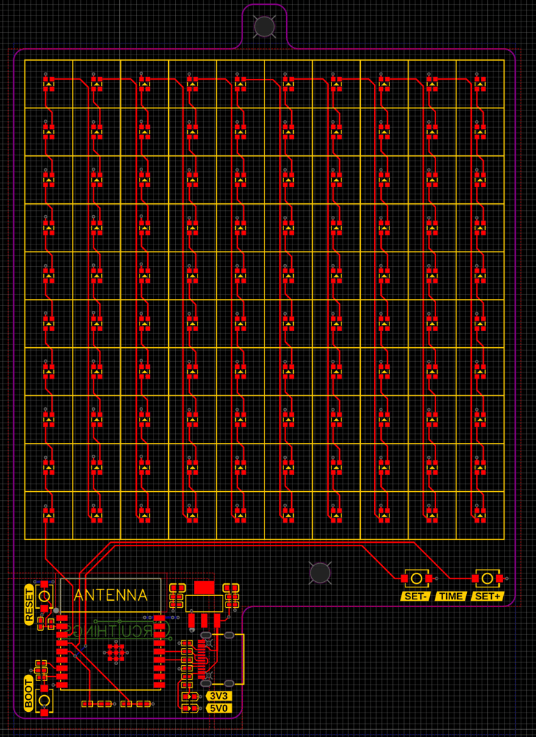
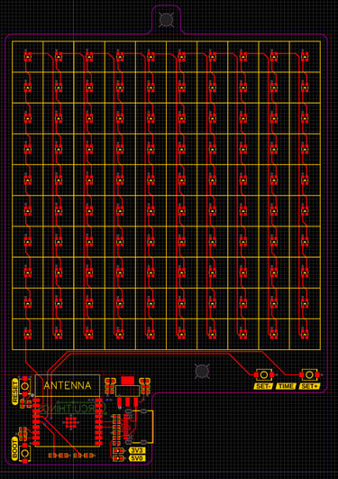
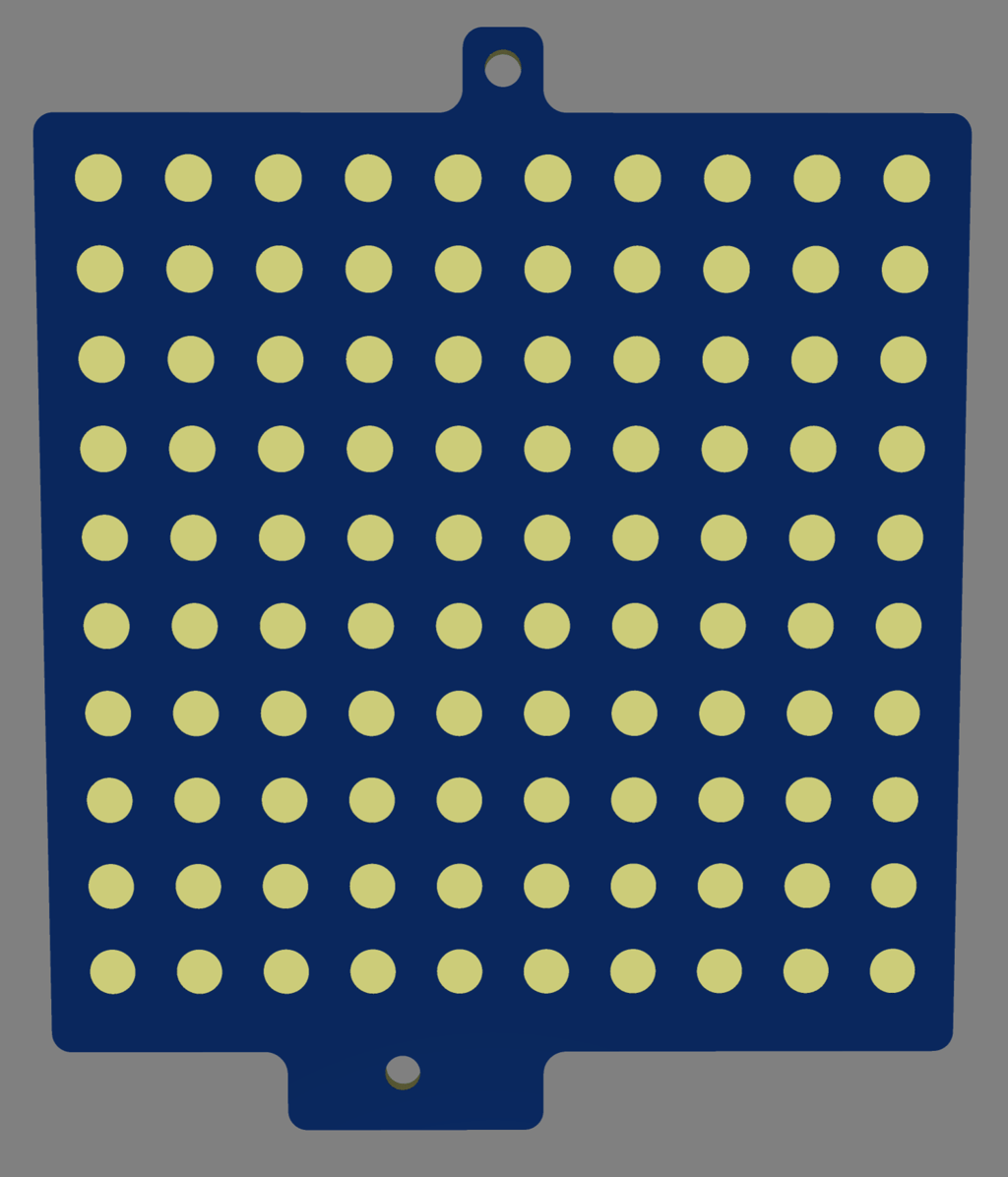
The layout of the baseboard is equally straightforward. Almost all routing of traces could be done on top layer. The bottom layer has a ground copper pour, while the top has two regions of copper pour, one for 5.0 V covering most of the board and one 3.3 V that covers the microcontroller region.


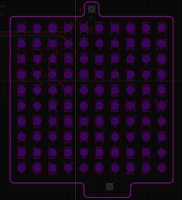
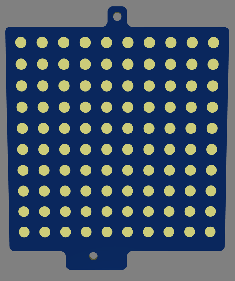
The spacer is just a PCB without any routing, only holes positioned on each LED.
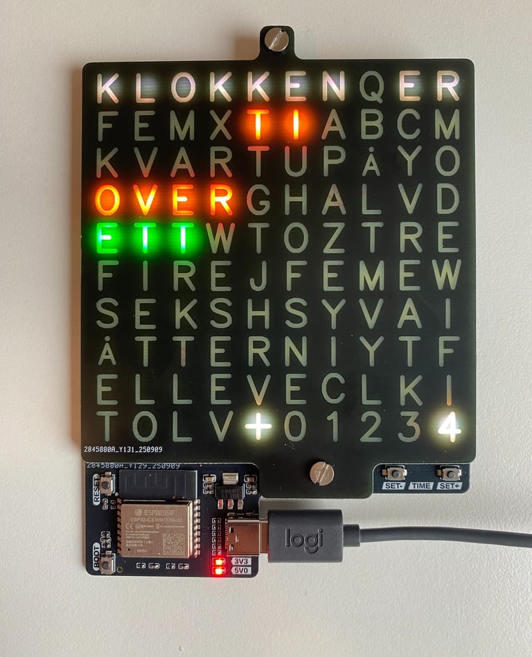
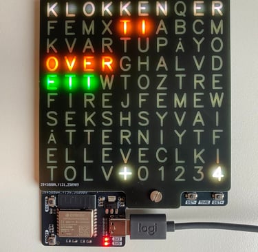
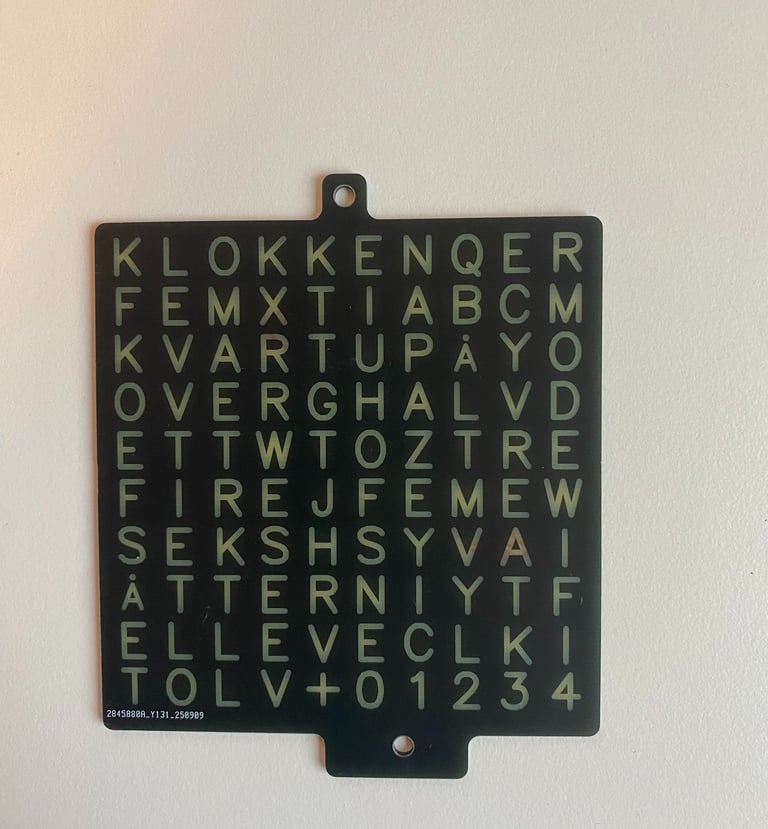
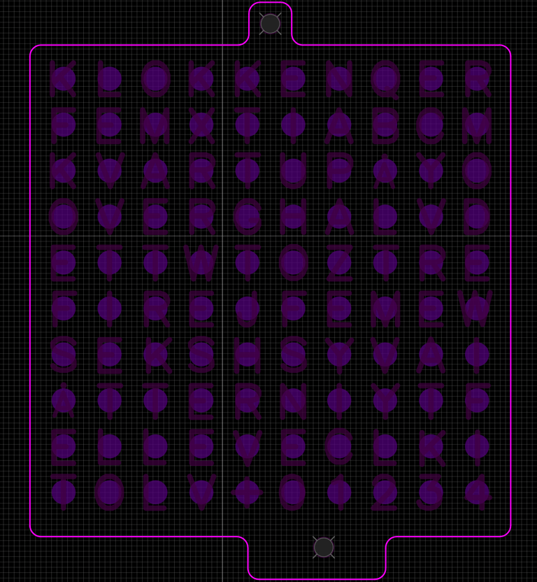
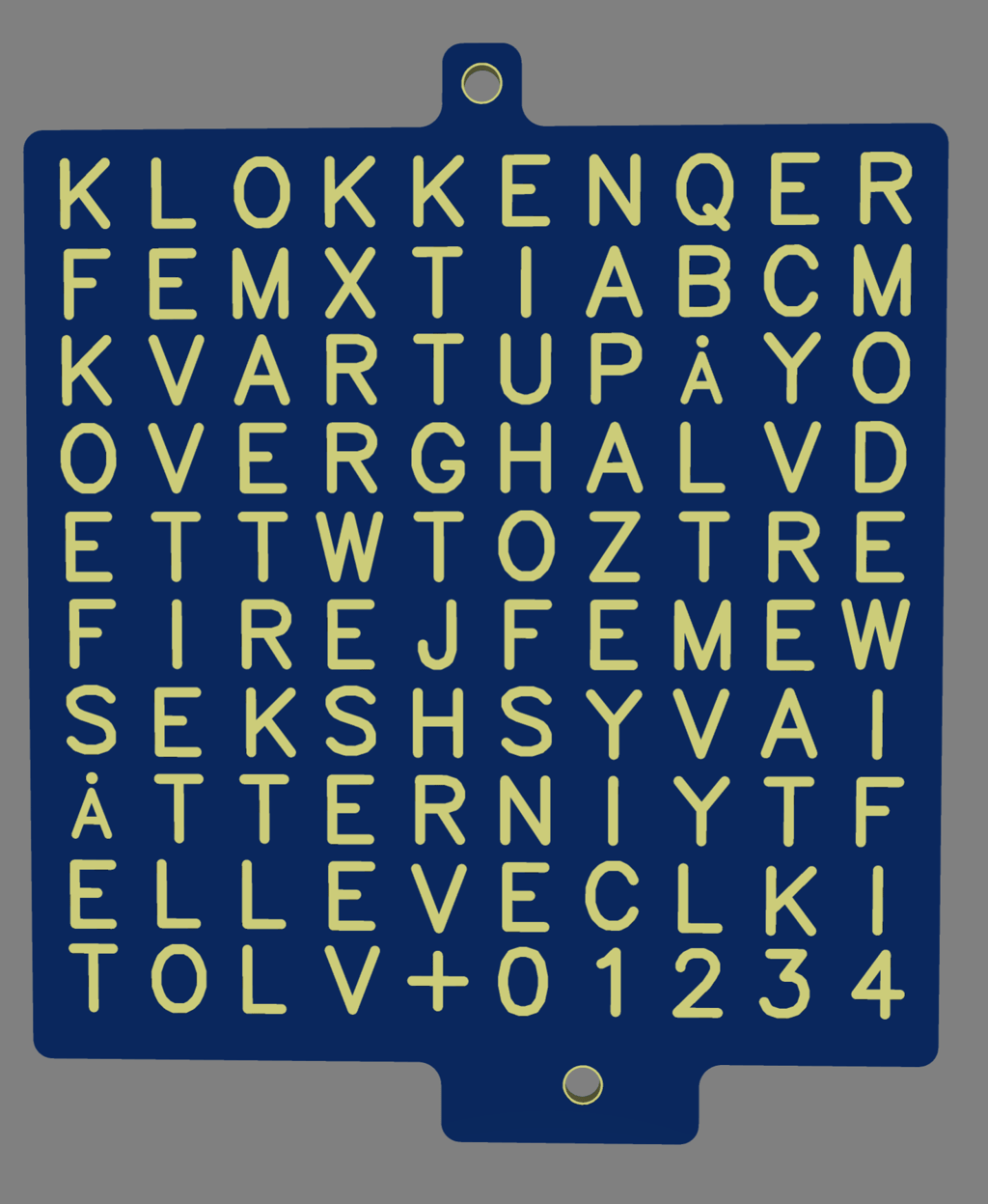
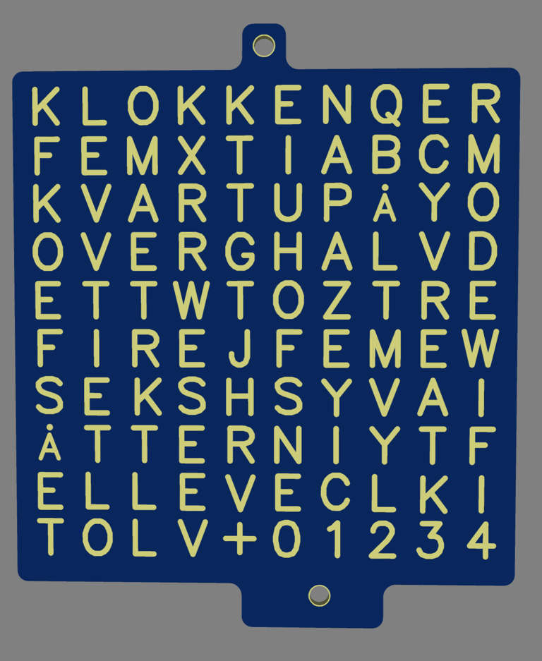
The frontpanel / mask PCB uses soldermask cut out shapes on the front to form letters, and holes on the back to let the light through. With 10x 10 leds it is not possible to spell out the time on a minute by minute basis, which is why it instead has 5-minutes intervals. The bottom row has the letters "+01234" which are meant to indicate how far along the current 5-minute interval the time is. The rest of the unused positions are padded with random letters that won't light up. I tried to spell WIFI on the rightmost row, thinking it could show an animation on those letters when the clock is connecting to WIFI (and in the process made a mistake, as the F in WIFI now became part of the word TF, which should be the word TI - norwegian for TEN.. Another thing to fix in the next revision!)
After ordering the PCBs with assembly from JLCPCB and receiving them, and verifying that they fit together when stacked onto each other, came the time to flash some code onto the base PCB. I used a Wifi library to enble the clock to connect to network and request time from a NTP server, and a time library for time formatting. An NTP time server is a server that uses the Network Time Protocol (NTP) to provide accurate and synchronized time to computers and devices over a network. These servers get their time from a highly accurate source, such as an atomic clock, and then distribute that time to clients on the network. I chose pool.ntp.org as it is a distributed pool, but there's many other that exist as well, i.e. both windows and google has their own services. The Adafruit Neopixel library works well for controlling the clock. The full code is shown below. Here's a short demonstration of it working
Circuithings
It's all about circuit things.
contact@circuithings.com
© 2025. All rights reserved.
Contact