Tic Tac Toe
A custom PCB using the ATmega328P microcontroller employs pogo-pins to receive capacitive touch user inputs from a PCB frontpanel, with a shift register controlling LEDs to backlight the same frontpanel. A third PCB is used as a spacer.
After finishing a few projects that showcased how the ESP32-C3-WROOM module could be used to realize both a wordclock project and a NFC reader project, I decided to follow up with creating a project that could give an example of incorporating the ATmega328P microcontroller as well. There's a couple of hobbyist tricks that I figured I could include as well to give this project a bit more content, namely using pogo-pins to connect to a capacitive touch panel, and re-using the same backlighting technique as I used with WS2812B RGB LEDs in the wordclock project, but this time using the much cheaper shift registers and single color LED instead.
The complete project consists of three PCBs, but only the bottom one has components assembled onto it, although capacitive sensing of user input is done on the top PCB. The more common way to get signals from one PCB to another is to use board-to-board connectors, but that means you have to have both PCBs assembled either by yourself or by a manufacturer. I prefer to use the JLCPCB assembly service, but cost-wise that means I want to keep the number of PCBs that has components on them down. The way this board-to-board connection is achieved instead is by connecting the top and bottom PCBs with pogo-pins and exposed copper pads. That enables ordering two very cheap PCB's and only one PCB needing assembly.
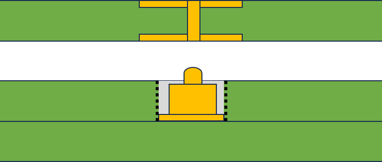
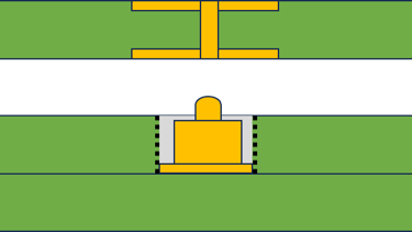
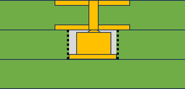
The key part here is that JLCPCB has a pogo-pin part that is 2 mm when not compressed, and 1.50 mm at maximum compression. With a standard PCB being 1.60 mm thick, that gives enough tolerance to be confident that using a PCB spacer will let the pogo pin be pushed in within its working distance, while also ensuring good contact with the copper pads. If you're interested, the partnumber for the pogo-pin I used is YZ153915020R-01. Here's a sketch of how it works, and the individual PCBs I used. It's important to note that the top PCB itself isn't heavy enough to keep the pogo pin compressed, so adding mounting screws to keep the board pressed together is recommended.

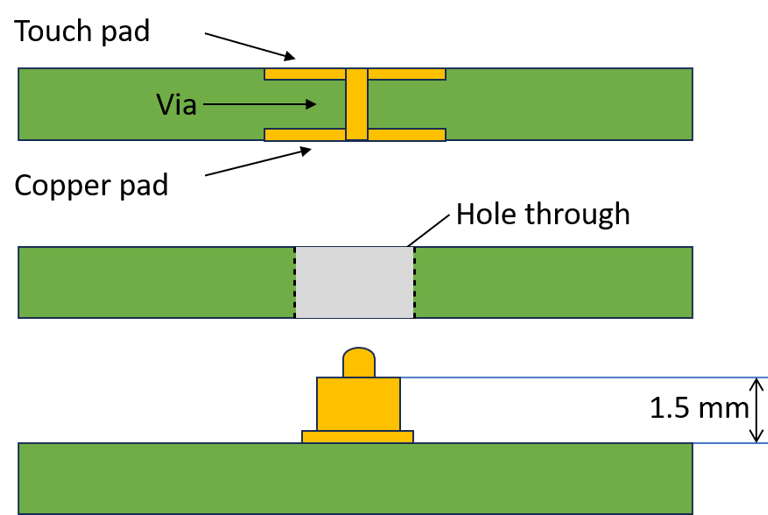
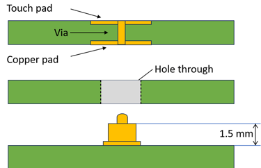
The three PCB's before stacking
The three PCB's after stacking the spacer on top of the bottom PCB
The Completed stack with connection from the touch pad on top to the electronics on the bottom PCB via the pogo-pin
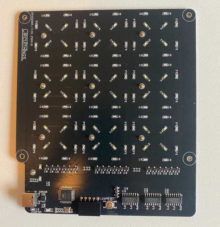
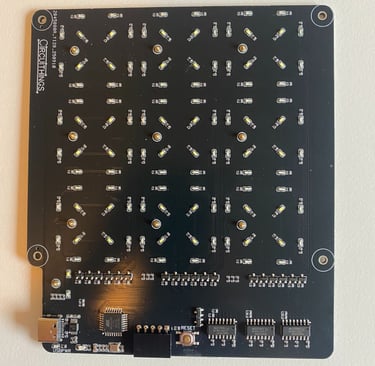
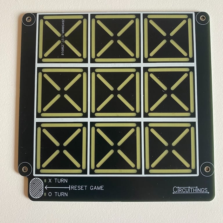
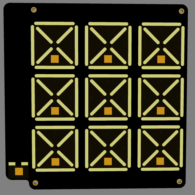
The base board with all the elctronics and LEDs and pogo-pins
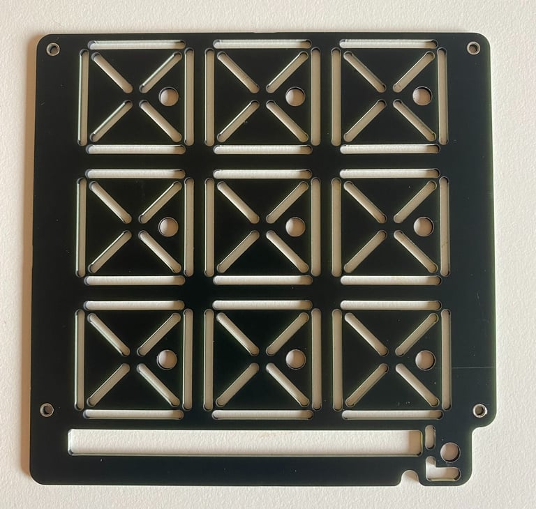
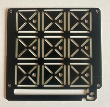
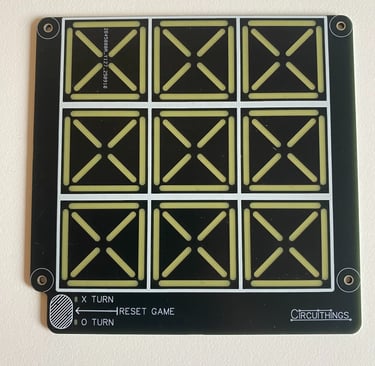
The spacer board with holes drilled for the elctronics and LEDs and pogo-pins
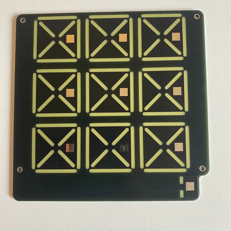
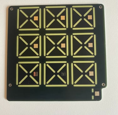
Front and back side of the top board with exposed copper pads for the pogo-pins and removed soldermask for the the LED's.
The schematic consists of several building blocks.
The first is the USB-C connector, which delivers power and allows communication with the PC for programming. It uses the same CH340E USB-to-UART chip that was used in the minimal demo board project. It connects to the serial pins on the ATmega328P microcontroller. That microcontroller exposes the SPI and Reset pins to a female header to allow flashing the Arduino bootloader onto the board on first use. The ATmega328P has the usual supporting circuitry with decoupling capacitors, oscillator, and reset button.
The second part is the pogo pins attached to the GPIO pins of the microcontroller. The pins sense capacitive touch using a capacitive sensing library made for AVR architecture microcontrollers. The way it works is by measuring the time it takes for a pin to change state when connected through a resistor to another pin. It does this by directly manipulating AVR registers for fast calculations (since the Arduino functions pinMode, digitalRead, and digitalWrite are too slow, and therefore only used for setup). It's therefore necessary to tie all the pogo pins to a common GPIO pin via a 1 MΩ resistor to make it work.
Each tile has LEDs beneath it that either light up a red O or a white X. This is done with regular LEDs, where a group of either 4× white or 8× red LEDs are controlled by a single signal via a transistor, requiring two signals to control one tile. In addition, there are LEDs that control the backlight to indicate whether it's X’s or O’s turn. This requires more signals than there are available pins on the microcontroller, so a couple of 74HC595D shift registers are used, reducing the required pins from 20 to 3.
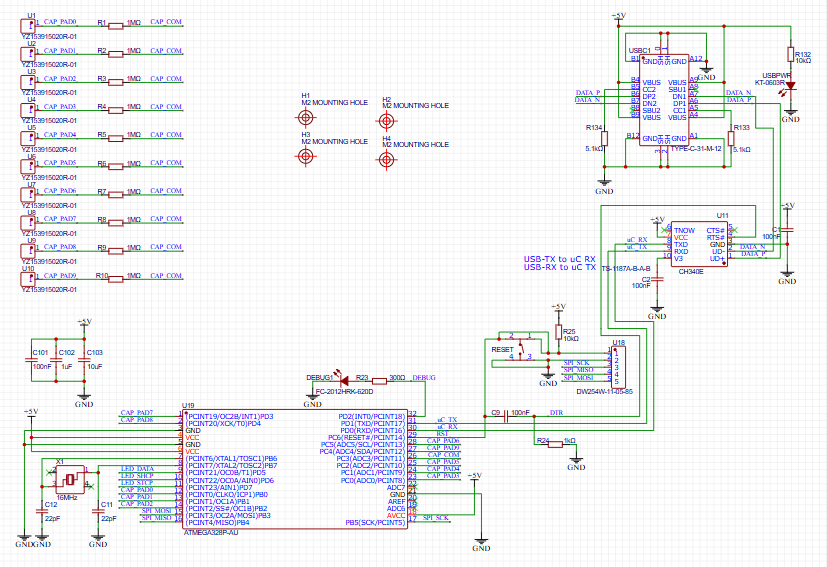
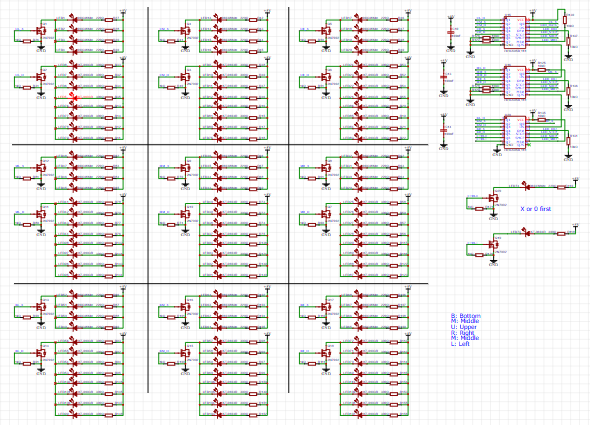
Page 1 and 2 of the electrical schematic. Page 1 has the microcontroller and USB-C and pogo-pin blocks, while page 2 wires up LED control
The layout of the base board with all the electronics is done on a 2-layer PCB. The component placement and alignment were the most time-consuming parts of the layout, while the actual routing of traces was fairly straightforward, given that there are no critical signals besides maybe the USB lines that need careful attention. The grey areas are the Document layer, which doesn’t get generated into the Gerbers but is useful for component placement. As usual, the bottom layer has a GND copper pour, and the top layer has a 5V copper pour.

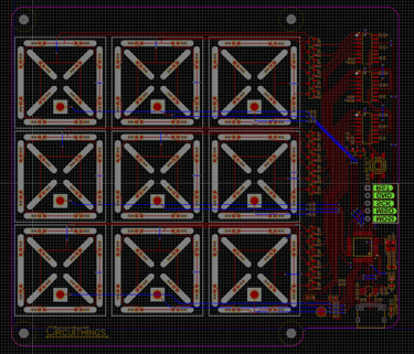
The layout of the baseboard
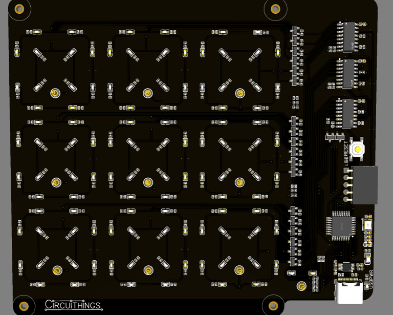
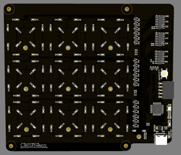

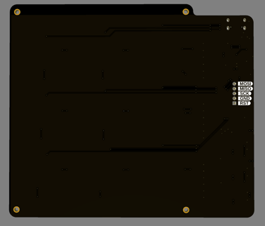
3D renders of the front and back of the baseboard
The electrical design of the spacer board is basically four screw holes, while the placement and drilling of holes and cut-outs are all done in the layout.
Layout of spacer board. Grey zones are cut-out zones, which are combined with holes to make the final hole shapes. 3D renders shows how it will look when produced
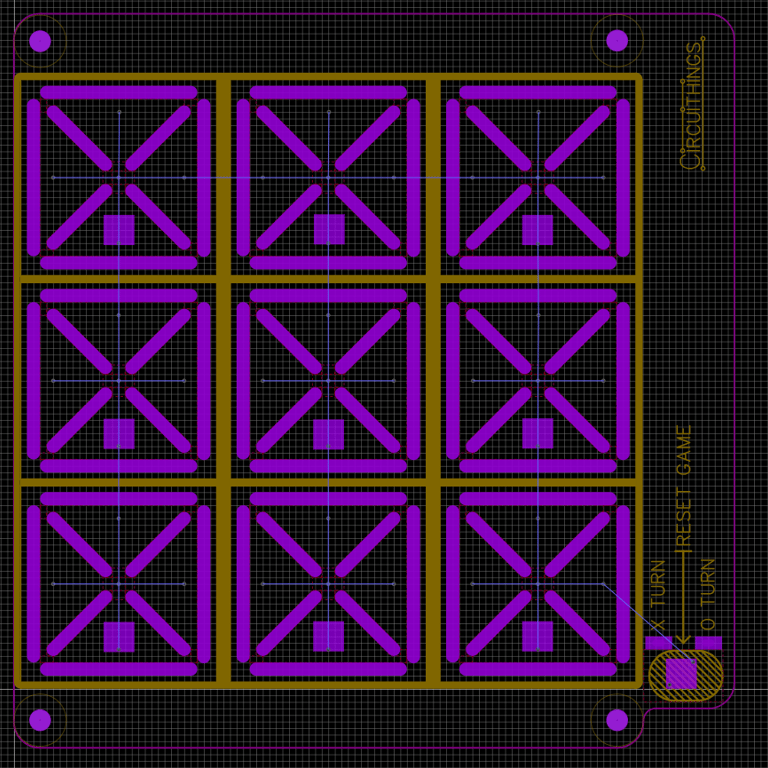
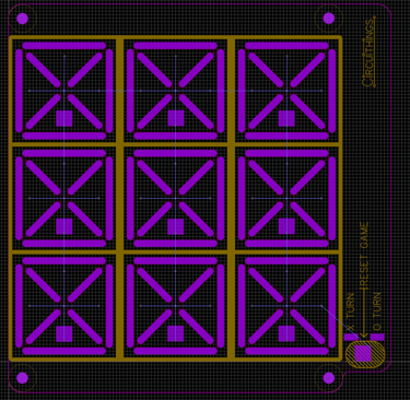
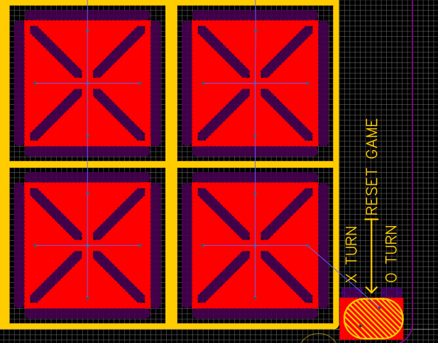
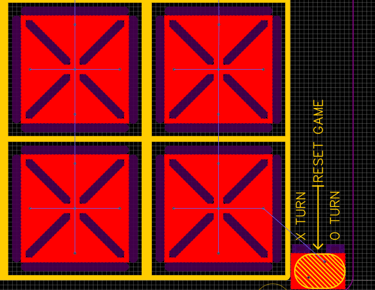
Layout of top board, showing removed soldermask on bottom, and a zoomed in detail of the copper pour on the tiles
The top PCB, just like the spacer PCB, doesn’t have any electrical components. It only has the solder mask removed where the LEDs shall shine through, mounting holes for screws, and some gameplay elements in silkscreen. The exposed copper pads on the bottom connect via vias to large copper pours that cover the game tiles.
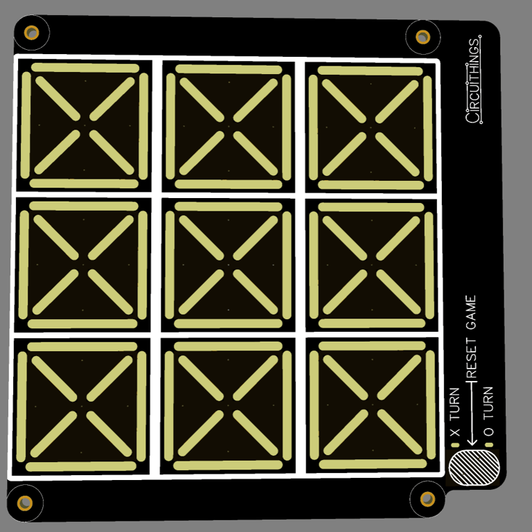
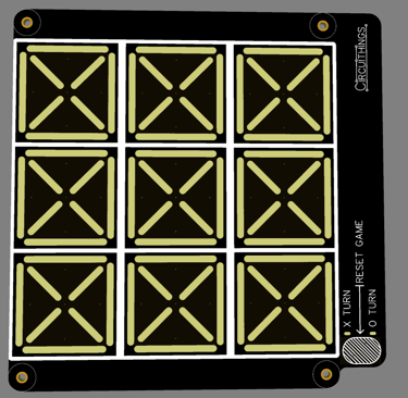
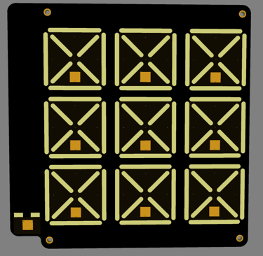
3D renders of top and bottom of the pcb
I got a surprise once I received the finished manufactured and assembled boards: I couldn’t connect to the microcontroller at all. The CH340E didn’t show up as a COM port, and no matter how many USB cables I tried or how many times I reinstalled the drivers, it didn’t appear. Eventually, I checked the USB enumeration using Microsoft’s USB Device Viewer diagnostics tool. It did show up (with Device Address 0x0C) but with the state “Current Config Value: 0x00” and the error message “!ERROR: No open pipes!”. So something was there, but Windows couldn’t negotiate with it to get it functioning. The vendor ID and product ID also didn’t match the expected values, so I ended up suspecting I had received something other than a functioning CH340E.
At this point, I decided I wanted to get the board working, not debug an issue I didn’t really know how to resolve. The USB port still delivered 5V, and the bootloader flashing header was still there, meaning I could just continue using the same Arduino Uno I used for bootloader flashing as a programmer and flash code via the SPI interface. That meant losing the serial connection (and thus serial console debugging), but the board and functionality are so simple that it turned out not to matter at all.
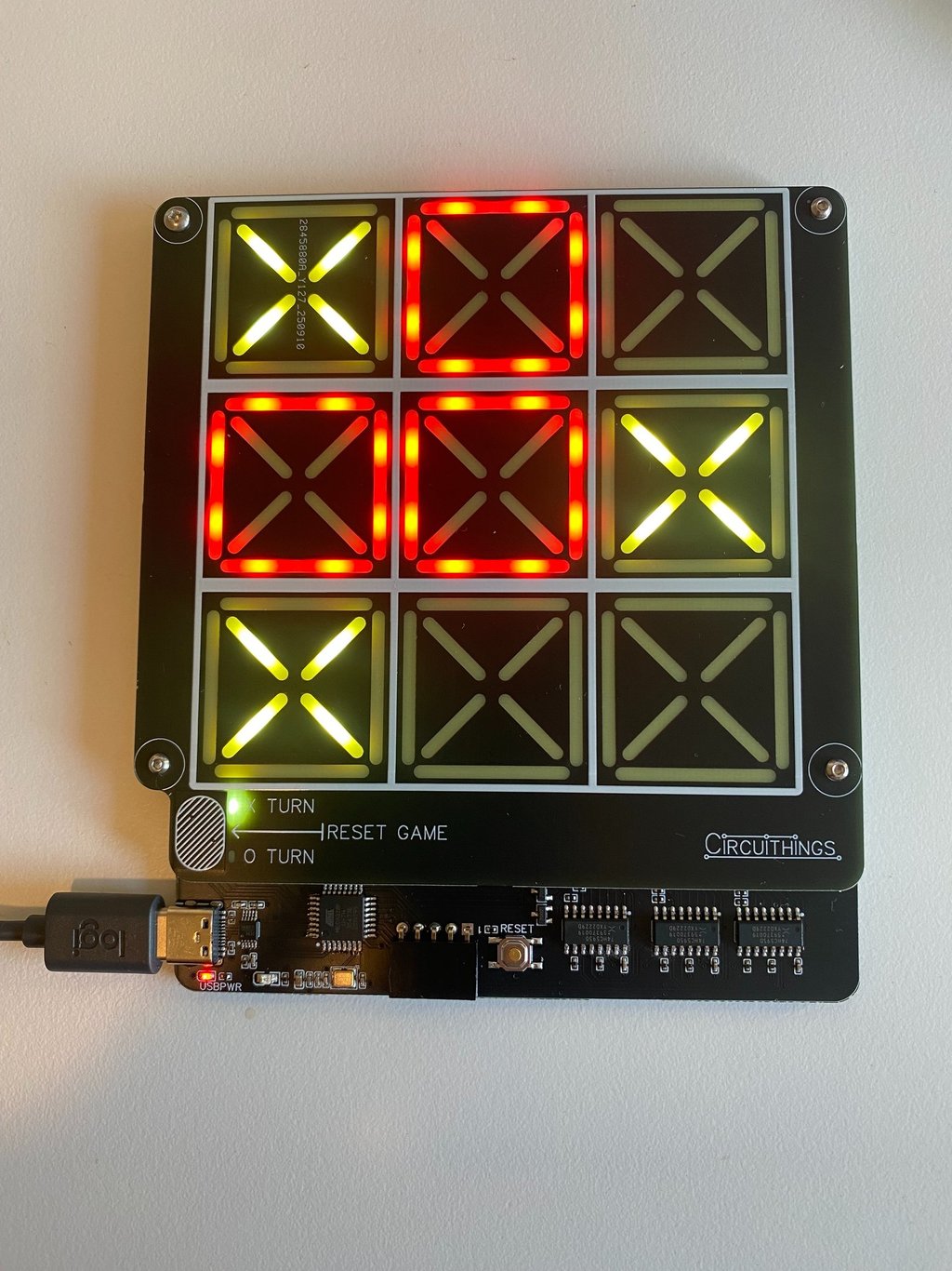
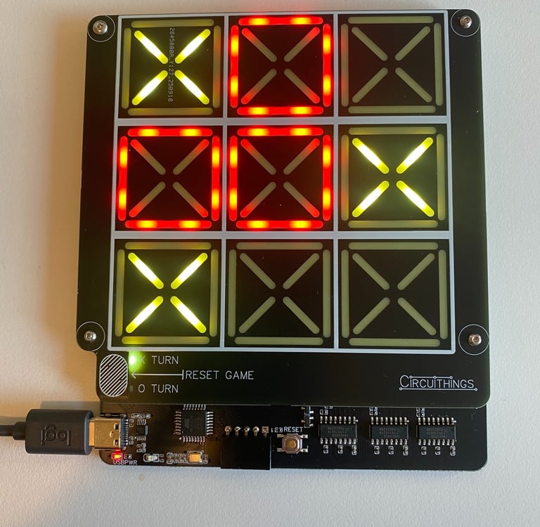
The game works as follows:
At first power-on (or after pressing reset), the game initializes, sets X as the first player, and clears all tiles. Then it waits for a touch on any of the nine tiles. When detected, it lights up that tile with X, updates the game state array with X at that position, and checks if any of the win conditions are met.
If no win condition is met and there are empty tiles left, it switches to the O player and repeats the loop. Once a win condition is reached (three in a row), a victory animation plays, and nothing else can happen until reset is pressed and a new game begins. If there’s no winner after all tiles are filled, a tie animation plays, and nothing else can happen until reset is pressed and a new game begins. Below is a GIF showing how it looks when X wins and reset is pressed.
The code is short, as the game is quite simple. The victory and tie animations are my own variants and can be tailored to personal preferences without affecting the gameplay.
Circuithings
It's all about circuit things.
contact@circuithings.com
© 2025. All rights reserved.
Contact