Creating and Programming a custom PCB with an ESP32-C3-WROOM
9/11/20257 min read
This is a follow up to my previous walkthrough on making custom ATmega328 development boards. Making a custom board with the ATmega328 is the natural step up from using the official Arduino boards, such as Uno and Nano and so on. But once you've both run into the limits of the ATmega328's capabilities, and mastered the art of making your own boards, it's typically time to move on to more advanced microcontrollers. A very popular choice for hobbyists is the ESP32 microcontroller made by Espressif. They have range of controllers specialized for different purposes, and common for all of them are that they outperform ATmega328 by a large factor in almost all aspects. For one thing, they are much faster, being 32 bit vs ATmega328's 8 bit, and the clock speed is typically 6-8 times faster. Another very important advantage is the massive upgrade in memory, both flash and RAM. This means you can write much larger programs, and they run much faster. There's also a much broader range of peripherals for the ESP32, ranging from native usb to high resolution timers to multiple UART/I2C/SPI, etc. The ATmega328 might compete with better deep sleep performance, and comparable number of GPIO, but the main attraction for many hobbyists is the Wireless capabilities of the ESP32 variants. While ATmega328 doesn't have any wireless capability, the different ESP32 variants all have WiFi and Bluetooth and some even have advanced capabilities such as Zigbee and Matter functionality. The cost of a ATmega328P-AU chip on JLC is about $2. One of the mid-range variants of the ESP32 is the C3, and the bare ESP32-C3 chip costs about $2.2, while a ESP32-C3 module with integrated RF antenna, called a WROOM module, costs about $3. All in all, the advantages of the ESP32 means it is a better choice in almost all cases for a hobbyist, especially since it has extensive Arduino support and can be programmed directly from the Arduino IDE.

This post is all about repeating what we did for the ATmega328 in a previous post, namely creating a custom PCB with an ESP32 microcontroller that is programmable in Arduino IDE, and can serve as a basis for subsequent projects. The first thing to do is look at the different offerings of ESP32 variants and choose one to work with.The original ESP32 is NRND (not recommended for new dseigns), but a few other variants have superceded it. I've chosen the ESP32-C3-WROOM-02-N4 for this post, and that's mainly because it is available in the integrated WROOM package in large quantities at JLCPCB assembly service, for economic type assebly (that's the cheapest assembly service). Other variants such as ESP32-S3 and ESP32-C6 and ESP32-P4 are all good choices, but for this post I have excluded them for various reasons. The -S3 is not availiable at JLCPCB for economic assembly in the WROOM package at the moment, and the -C6 is a newer and more expensive chip that doesn't have the same range of examples and hobbyist use as of yet. The ESP32-P4 is a very different type of chip with rich user interfaces such as camera input, displays, and video processing, and a lot of GPIO and complex peripherals (USB OTG, Ethernet). It is meant for higher compute performance for edge AI and signal processing, and comes at a higher cost, while the -C3 and -C6 are mainly meant for wireless connectivity, low power consumption, low cost, and simple deployment. But all the -S3, -C6, and -P4 variants might be worth their own separate post at a later time though.
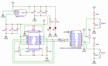
So the first thing to do when making a schematic for the ESP32-C3-WROOM is to look at the reference design in the official Espressif documents. The easiest way top find a complete reference design is to look at the newest version of the official development board for the ESP32-C3-WROOM, which is the ESP32-C3-DevKitC-02. Esspressif has the schematic for it readily available for us at their website, and we can have a look at what's needed there:
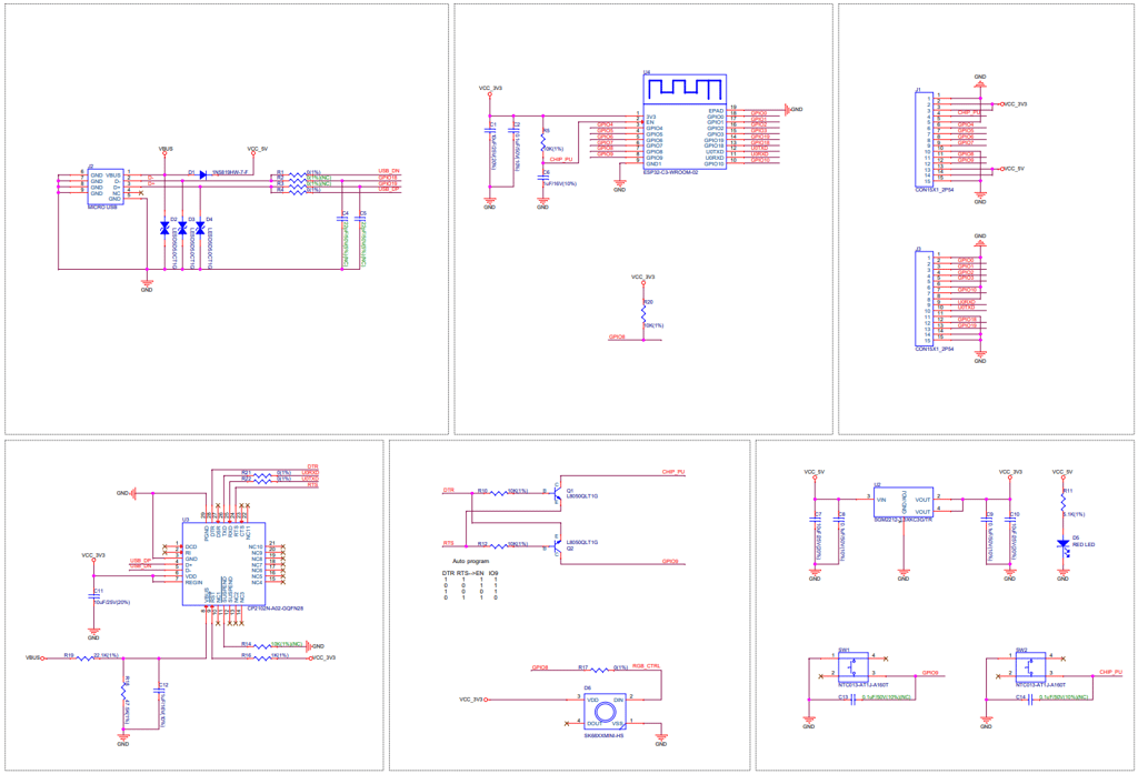
The reference design uses a Micro USB connector and splits the USB lines to both the USB interface on the ESP module, and to an usb-to-uart converter that again interfaces to the ESP module's serial interface. The first adaption we will want is to replace the Micro USB connector with a USB-C connector. Second, since the ESP32-C3 chip now has support in Arduino IDE for direct USB programming, and so-called CDC USB functionality (which basically means we can get Serial data from USB directly), we can remove the whole usb-to-uart part with the CP2102 chip and just have the datalines from the USB-C connector hooked up to the ESP32 module and nothing more is needed. That also means we don't need the double BJT transistor circuit since it is there to enable programming over serial interface, while the USB interface doesn't use it.
The voltage regulator is still needed, but the SGM2212-3.3 IC is an extended part at the JLCPCB assembly component library (meaning it costs extra to use it), while the AMS1117-3.3 is a basic part, so we will go with the AMS1117-3.3 instead.
That leaves us with the RGB led and the buttons. We'll keep the LED to help with debugging, but change it to the more common WS2812B type, and throw in a few more just to have more flexibility with how we can display information. We'll keep it at GPIO8, together with the pullup at GPIO8. The pullup is there because GPIO8 is a so-called strapping pin for the ESP32 module. The ESP32 looks at the state of the pin at start-up to see which configuration it should startup with. As long as we use GPIO as a datapin for the RGB led, that means it will be pulled up at start-up, and free to use as ouput for us after start-up.
We copy the button functionality more or less, giving us the option to do a manual reset on the EN pin, and set boot configuration on the GPIO9 pin. This is a remnant of an older issue with the ESP32 chip, where pulling down the boot pin to ground before startup was needed for entering a mode where it could be programmed. But the more modern ESP32-C3 has a built-in native USB peripheral, which can act like a USB device directly, and in Arduino IDE the native USB bootloader can be triggered without manually toggling GPIO9 if the firmware and IDE support automatic USB bootloader activation. So essentially, the IDE communicates directly over USB and can command the chip to enter bootloader mode and bypass the old BOOT=LOW requirement. We want to program directly over native USB with Arduino IDE, so we could in theory remove the whole button. But in practice it's nice to keep it as it lets us recover if the chip gets stuck in a weird state, and it let's us use alternative flashing tools or older IDE versions, and it doubles as a input button after start-up of the chip is complete. The last is especially nice, since it means our demo board will have a user input button for debugging.
That's it, the required schematic ends up a bit smaller and quite easy to implement on a PCB!

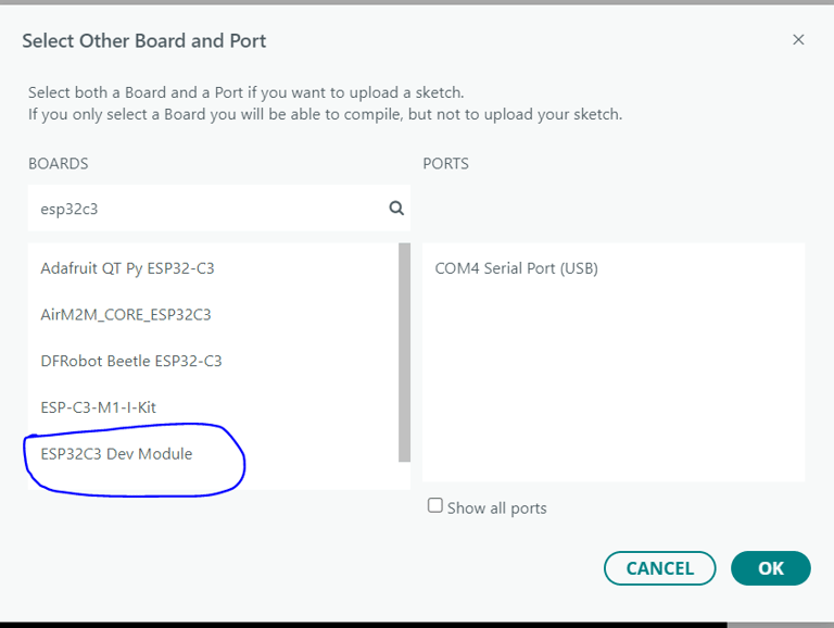
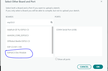
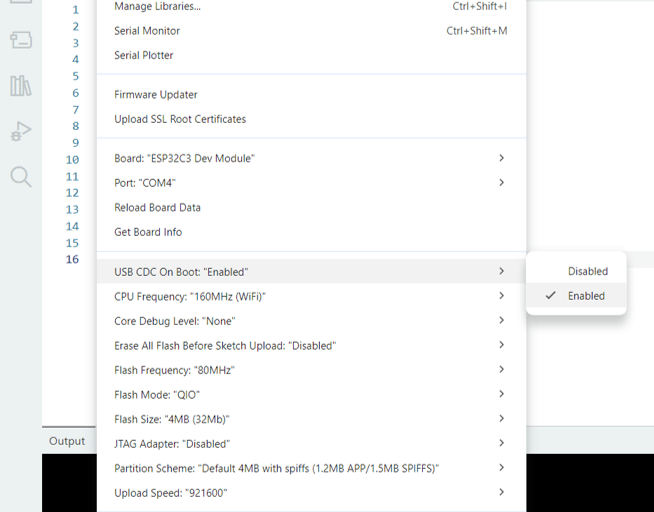
The settings needed to program your custom ESP32-C3-WROOM board in the Arduino IDE is:
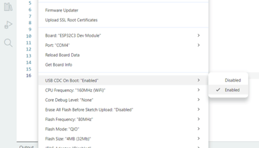
The setting needed to get serial communication over USB is setting SB CDC On Boot to Enabled in the Arduino IDE:
Thats it! Although you might or might not encounter some erratic behaviour from the USB the first time you use the module. It is common to experience the USB connection to connect and disconnect repeatedly the first time you connect it to your computer. There's multiple possible reasons for this. One could be that the factory-firmware that already is on the chip when it comes from the manufacturer doesn't interact with the automatic USB bootloader circuitry inside the chip. Or there's programmed in a watchdog timer that runs out very quickly and resets the chip. Or something else. But there's two ways around it. One is to try and upload a sketch and hope you manage to get it compiled and uploaded before the USB disconnects (can be a bit frustrating.) The other is to use the RESET and BOOT buttons (good thing we included it after all!). Get into the firmware programming mode by holding BOOT, press and release RESET, wait a second, and release BOOT. Now the chip booted up while seeing the BOOT signal being low (compared to default state being high). This forces the chip into a mode where it doesn't execute the code that's already on it, as well as waiting for a new firmware upload. Once you've uploaded code (can be as simple as an empy sketch) using one of these two methods, press the RESET button to restart the module, and you shouldn't have any more problems!
Circuithings
It's all about circuit things.
contact@circuithings.com
© 2025. All rights reserved.
Contact