From prototype to custom PCB - NFC Reader
NFC reader PCB based on MFRC522, with an integrated ESP32-C3-WROOM microcontroller on board
This project is intended to show a few things. It will show how to make your own custom ESP32-C3-WROOM board, just as described in this post. It will also show how you go in steps from prototyping with modules to integrating the modules together to make your own board with exactly the functionality you need. In the end of this project, we'll end up with a custom PCB with a NFC frontend chip MFRC522 and antenna, interfacing with an ESP32-C3-WROOM microcontroller, for reading simple Mifare tags.
I recently found myself interested in Near Field Communication (NFC) technology, and wanted to understand enough of it to make my own NFC reader. I dived into it, and the resulting overview I got from it is written in this and this post. The next thing to do once I had an idea of what I wanted to try, was to prototype. I chose the RC522 NFC module and an ESP32-C3-DevKitC-02v1.1, and went and bought them and wired them up with Dupont wires
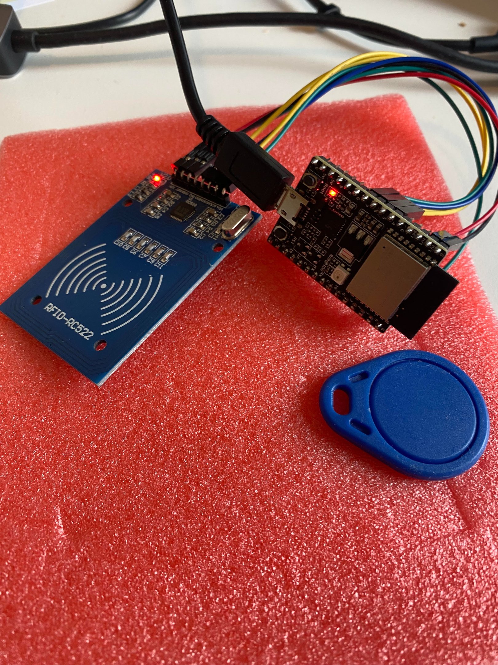
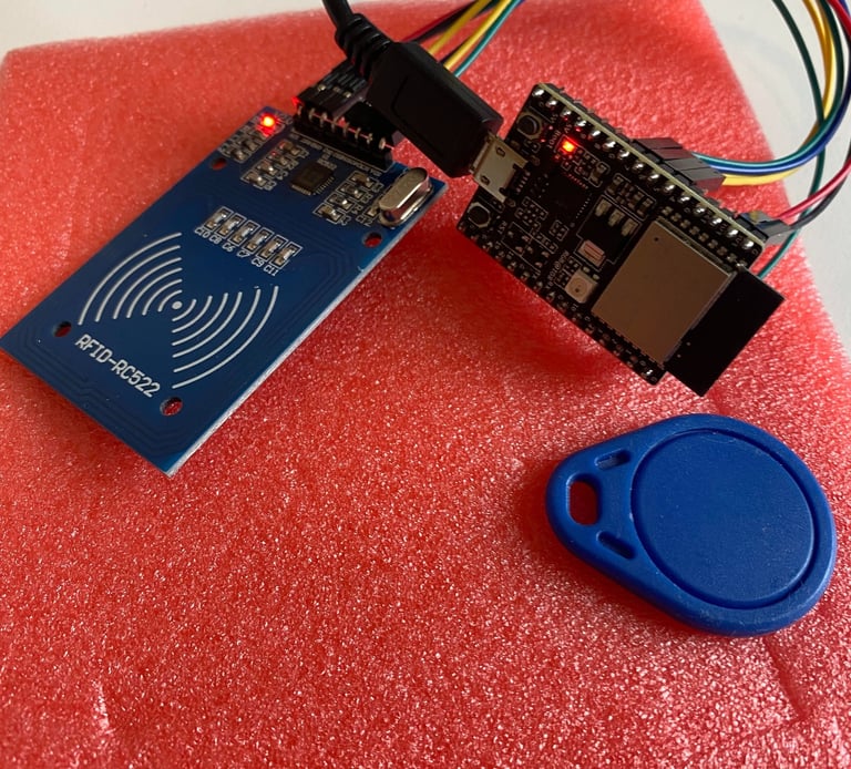
and tried it with the ESP32-C3 devboard the way it was shown in various guides and YouTube videos. The first board worked fine with the RC522 library written by Miguel Balboa. The library in use can be found through normal library search in the Arduino IDE (if you don't know how, there's info on Arduino.cc that explains that much better than me). The link to the library GitHub page is https://github.com/miguelbalboa/rfid/tree/master.
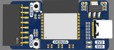
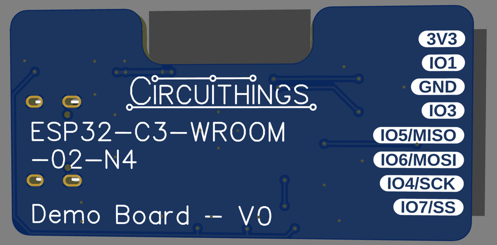
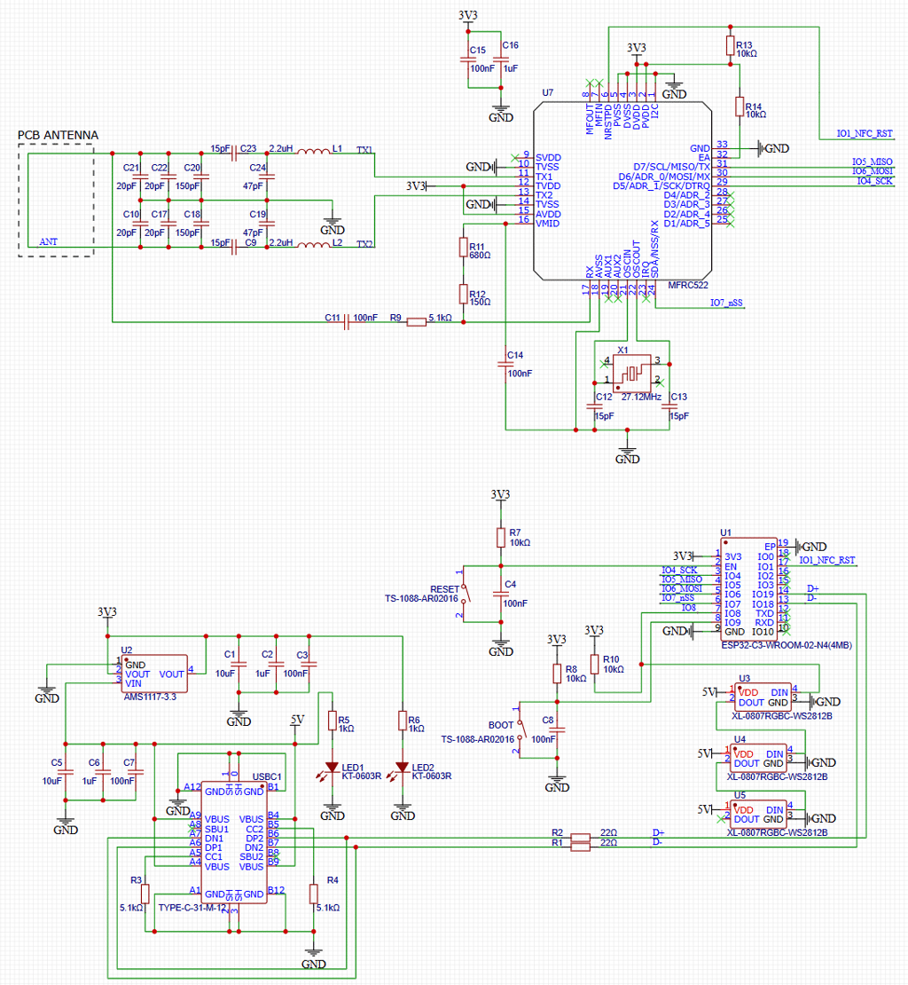
After confirming that the setup with two bought modules works, it's time to replace one of them with my own custom PCB and see if it still will work. I chose to first try to design my own ESP32-C3-WROOM board, and see if I could get it to work with the RC522 module. I followed the schematic from my own post and added 3x WS2812B RGB LEDs for debugging, as well as exposed the same 8x pins as the RC522 needs connected on a 8-pin female header, so that the RC522 module can be plugged directly in.
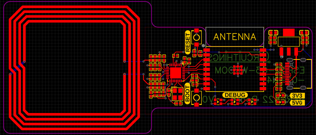
The layout of the board is not complicated, the only real important part is to make sure the USB traces are short. The bottom is filled with ground pour, and the top is filled with 3.3V pour.
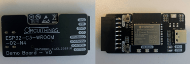
The finished assembled board looked good, so time to test it.

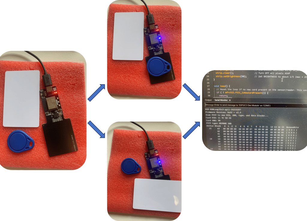
The board worked without trouble right out of the box it came in, which means it was time to see if it also would work fine when integrated with the RC522 module. I combined the "dumpinfo" example from the RC522 library with a bit of code for lighting up one of the NeoPixels when it reads a card or tag.
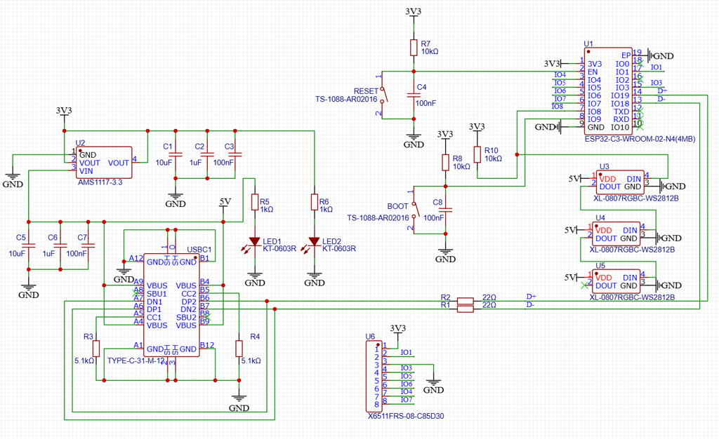
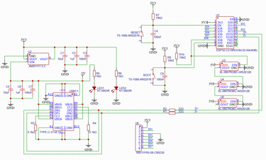
Next part of the project - recreate the RC522 module and integrate it with my working custom ESP32-C3-WROOM board. Luckily I found a schematic of the RC522 at ( https://circuitdigest.com/microcontroller-projects/interfacing-rfid-reader-module-with-arduino ) that looked like it could work. I tweaked it with some minor adjustments, like removing the ground connection from the antenna, and limiting myself to the basic assembly components in the JLCPCB library to keep costs down.
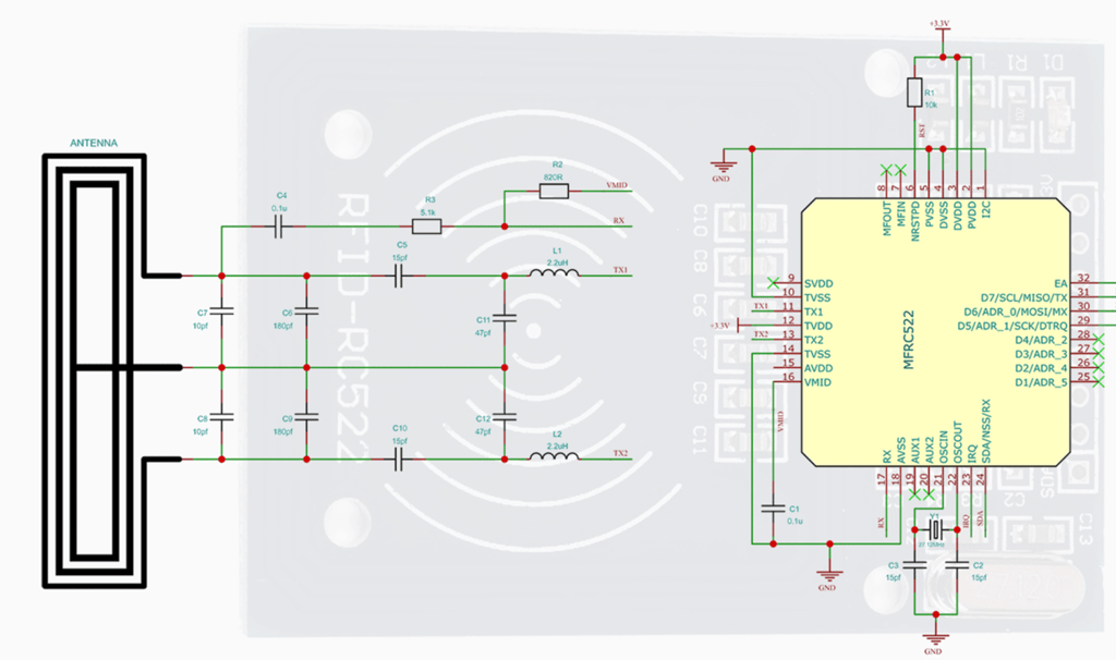
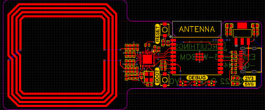
Here's the final combined schematic of my board and the RC522 module.

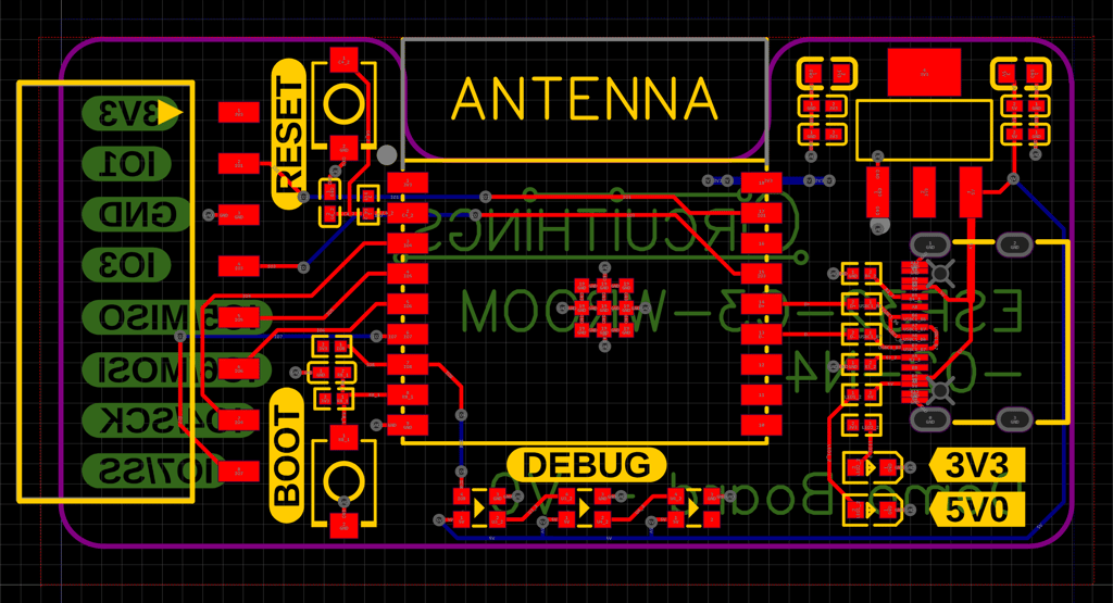
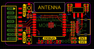
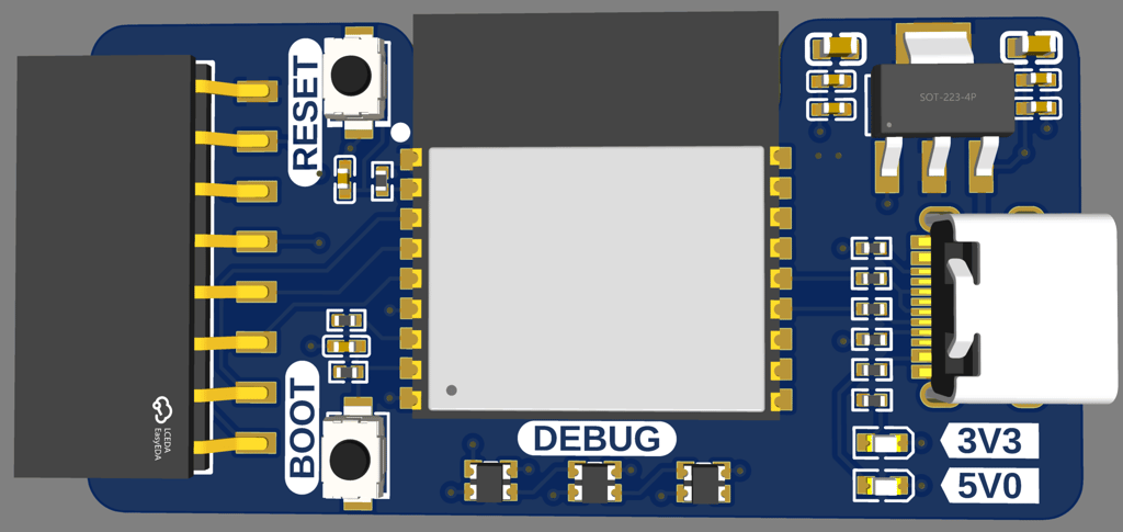
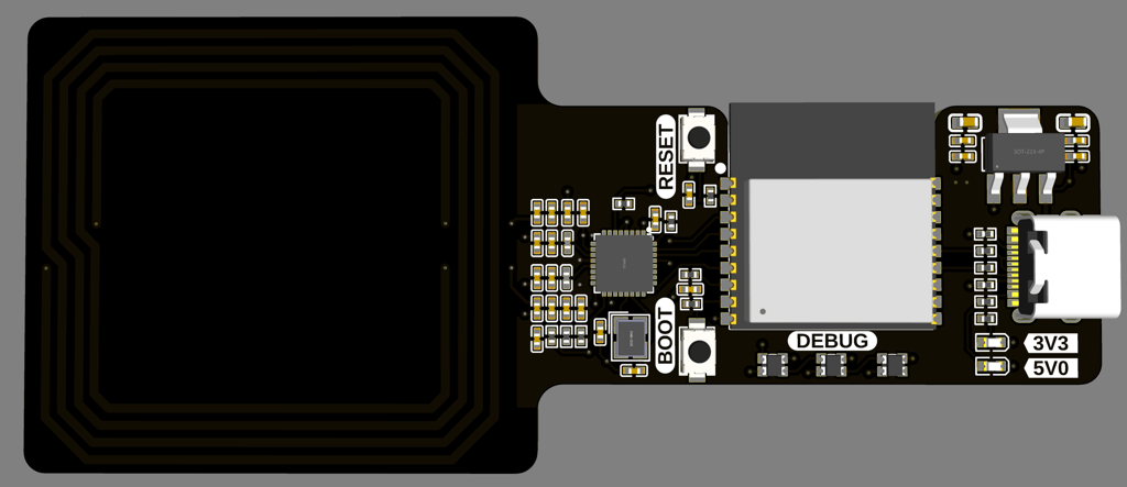
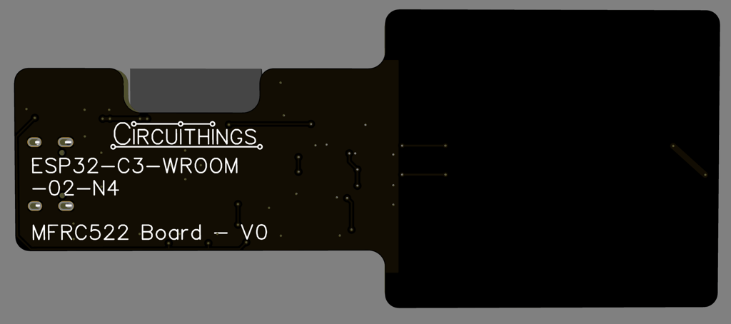
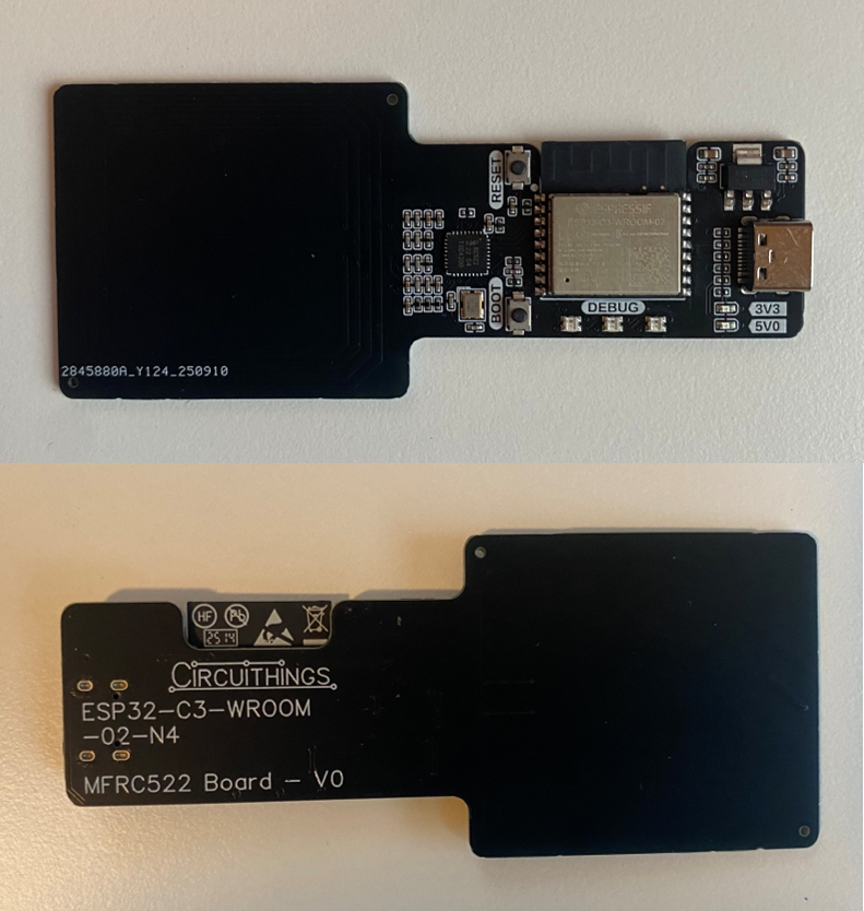
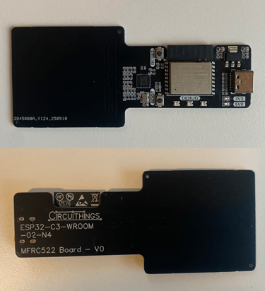
And the layout and 3D renders of the top and the bottom. For the layout part I've kept the antenna dimensions as close to the original RC522 module as I could, but the rest of the discretes and the MFRC522 chip placements are laid out to fit my design.
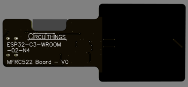
Once I got the finished design, I ordered it with assembly. Everything looked great once I got it!
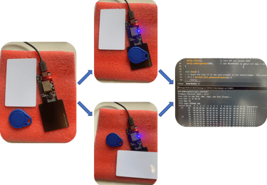
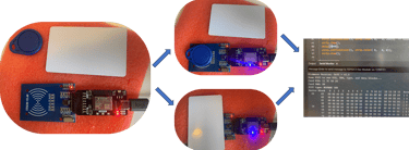
Now everything is ready for testing it. I used the exact same demo code as I used for the previous iteration. And it worked just as I hoped it would:
And that's it for this project. The intention was to show the process of going from a prototyping setup to a custom PCB with your own design, integrating modules and a microcontroller. This was a fun project that let me get up to speed on NFC technology, and hopefully also will be helpful for anyone who wants to try something similar but is unsure of how to get started. Below is the quick test code I've used in all testing in this project.

Circuithings
It's all about circuit things.
contact@circuithings.com
© 2025. All rights reserved.
Contact